OCAD Preferences
GUI (Graphical User Interface)
If enabled, the context menu is shown by clicking on the drawing area with the right mouse button.
In the upper part of the Context menu, you can switch between the current Drawing Mode, the Select and Edit Object mode and the
Select Object and Edit Vertex mode.
In the lower part of the Context menu, you can change the view either with the Pan,
Zoom In,
Zoom Out or the
Show Entire Map tool.
If disabled, you can switch between the current Drawing Mode and the Select Object and Edit Vertex mode by clicking on the drawing area with the right mouse button.
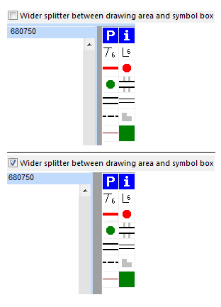
Wider splitter between drawing area and symbol box
If this option is enabled, the splitter between the symbol box and the drawing area appears wider as usual. This feature may improve the user-friendliness.
Toolbars
Show or Hide the following toolbars in this field:
- Editing and Drawing Toolbar
- Edit Functions Toolbar
- Mobile Toolbar
- Numeric Keypad Toolbar
- Standard Toolbar
- View Toolbar
Click the Customize button to add or remove icons to/from the toolbars.
Status bar
Choose the format of the coordinates appearing in the Status Bar in this box.

Style
Change the virtual appearance of the GUI by choosing one in the dropdown list.
File
Auto file load when opening OCAD
Check this box to load the last map you worked on automatically when OCAD is started. Otherwise no map will be loaded.
Auto file save
This option is not enabled when a map is loaded. Please close all maps before opening OCAD Preferences.
Check this box to save all changes to the original file automatically.
When this box is not checked, all changes are saved in a temporary file. When you close the file you will be asked if you want to save the changes to the original file.
This option has no effect for untitled files (new files which have never been saved to disk).
![]() In the mode of permanent automatic saving, the file is considered as "read only". If you want to save it, you are re-directed to the Save as procedure requesting a new name for the file.
In the mode of permanent automatic saving, the file is considered as "read only". If you want to save it, you are re-directed to the Save as procedure requesting a new name for the file.
View
Enter a value to specify the User Defined Zoom. Choose User Defined in the View menu to apply the specified zoom to the map.
View mode loop
With the View mode loop tool you can easily switch between different view modes. Select the view modes you want to switch between in the View mode loop box in the View category of OCAD Preferences.
To use the View mode loop you have to define a Shortcut for View - View Mode Loop. Afterwards you can switch between the set view modes using the Shortcut.
Color Correction
On some monitors colors and gamma of the map are not displayed correctly. Use the controller to regulate the color and gamma manually. Click on the Standard button to set the Color Correction back to default.
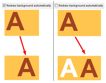
Redraw background automatically
If this option is enabled, the map is redrawn after every single modification of the map (This may reduce the performance of OCAD). Otherwise you have to press the F5 key or select Redraw in the View menu to redraw the map.
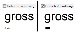
Faster text rendering
Enable the Faster text rendering option to render text faster and less precisely. This may increase the performance of OCAD.
Select
You can choose between two modes to select multiple objects:
- All objects must be with at least one vertex in the selection.
- All objects must be completely in the selection.
You can find more information about selecting multiple objects on this page: Select and Edit Multiple Objects.
Object
Object stretching
If this option is activated, you are able to stretch objects in the Select and Edit Object mode.
You can find more about stretching objects on this page: Select and Edit Object.
Unsymbolized objects
Choose a color for Unsymbolized Objects by clicking on the Setup icon. The Color Picker dialog appears and you can configure the color.
Drawing and Editing
Drawing Bézier curves
Choose the preferred mode for drawing curves.
- In OCAD mode, only the direction of a dragged tangent is used. The distance from the normal vertices to the curve vertices is calculated automatically. This is the recommended mode.
- In Illustrator mode, the length of the dragged tangent is used to calculate the distance of the curve vertex.
You can find more about drawing curves on the following page: Draw a Curve.
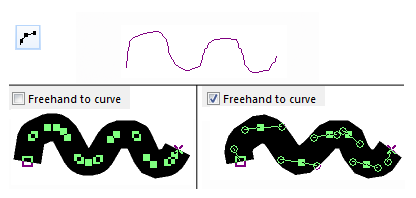
Convert freehand to curve when drawing
Check this box to convert lines and areas to curves when drawing in freehand mode. Otherwise they remain as polygons. The settings made in the Smooth when drawing freehand dropdown list of the Tolerances field determine the smoothing level.
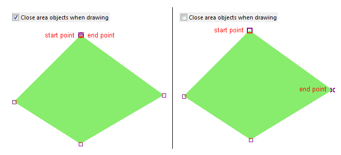
Close area objects when drawing
OCAD closes area objects automatically if this option is checked. If the start and end point are different, OCAD adds an end point with the same position as the start point.
Choose Close Area Objects in the Topology part of the Object menu to close already drawn area objects.
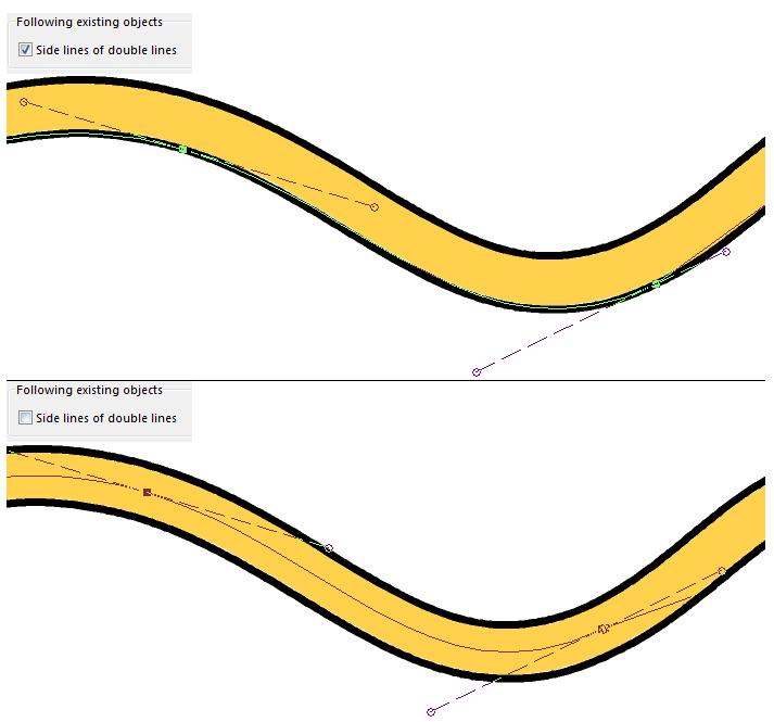
Following existing objects
Uncheck the Side lines of double lines option if side lines of double lines should not be traced when you are following existing lines. You can find more about this topic on the Following Existing Objects page.
Tolerances
- Select objects: This tolerance defines the maximum distance on each side of a thin line where you can click to select it. Objects with a thicker main line than the tolerance level can be selected by clicking on the entire line width. The default value is 3 pixels.
- Snapping: If you activate the Snapping tool, moving a vertex close to an objects has a snapping effect. This tolerance defines the maximum distance you have to approach to the object, so that the vertex snaps to it. The default value is 5 pixels.
 [Snapping]
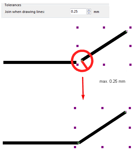
- Join when drawing lines: This tolerance defines the maximum distance a vertex has to approach to another line end to join it. The default value is 0.25 mm. If the line width is bigger than this tolerance then OCAD takes the line width as the tolerance.
- Smooth when drawing freehand: There are three smoothing levels for freehand drawing mode: slightly, medium and strong. They correspond to 0, 1 and 2 in earlier OCAD versions.
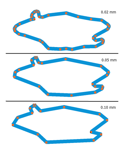
- Change to Bezier curve: This tolerance defines the maximum distance the vertices can move away from the original position by changing from polyline to Bezier curve. The default value is 0.10 mm. Note that the distance between the curve and the polyline can be greater between the vertices.
- Smooth (generalization): This tolerance is used by the Douglas-Peucker smoothing algorithm. Vertices that are closer to the direct line between the previous and the next vertex are removed. The default value is 0.05 mm.
Cursor color
You can change the cursor color to black, red, blue, purple or yellow by selecting a color in the dropdown list.
Mark
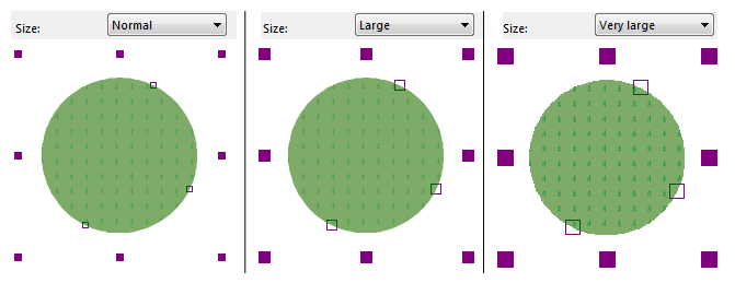
Set the mark size to normal, large or very large and choose a mark color by clicking the Setup icon.
Enable live preview
Enable this option to show the real line width when drawing line objects.
Auto scroll
Check this option if the map view should automatically scroll if you drag out of the drawing area. Uncheck this option if you have a slow PC.
Symbol
ToDo
Map
ToDo
Layout
ToDo
GPS
ToDo
Warnings
ToDo

