Example Railway: Difference between revisions
Jump to navigation
Jump to search
No edit summary |
No edit summary |
||
| Line 15: | Line 15: | ||
In Double line page: | In Double line page: | ||
# Choose Full lines for Mode. | # Choose the Full lines for Mode. | ||
# Enter the width of the | # Enter the '''color''' and the '''line width''' of the '''left line''' and the '''right line'''. | ||
[[File:RailwayDoubleLine.png]] | [[File:RailwayDoubleLine.png]] | ||
In the Framing page: | In the Framing page: | ||
# Choose the black color in Line color. Note that this color must be below the color of the dashed line in the color table, otherwise it will cover the dashed line. | # Choose the black color in '''Line color'''. Note that this color must be below the color of the dashed line in the color table, otherwise it will cover the dashed line. | ||
# Enter the width of the | # Enter the '''Line width''' of the framing line. | ||
[[File:RailwayFraming.png]] | [[File:RailwayFraming.png]] | ||
Revision as of 17:38, 8 May 2013
To create this symbol, start from an empty line symbol and then do the following steps:
In the Main Line page:
- Enter Line color and Line width.
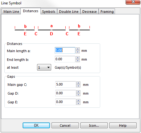
In Distances page:
- Enter the maximum distance between the lines as Main length a.
- Enter the length of the gap in the center line in Main gap C.
In Double line page:
- Choose the Full lines for Mode.
- Enter the color and the line width of the left line and the right line.
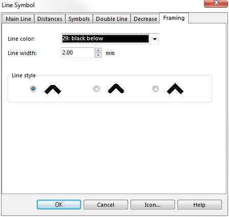
In the Framing page:
- Choose the black color in Line color. Note that this color must be below the color of the dashed line in the color table, otherwise it will cover the dashed line.
- Enter the Line width of the framing line.
Download link: [Example_Railway.ocd]
Back to Create a New Symbol


