Create a New Map: Difference between revisions
(/* Create a New Map File:Space.PNGThis function is available in OCAD Professional.|link=https://www.ocad.com/en/products/ocad-for-cartographyThis function is available in OCAD Orienteering Standard.|link=https://www.ocad.com/en/products/ocad-for-orient...) |
(/* Create a New Map File:Space.PNGThis function is available in OCAD Mapping Solution.|link=https://www.ocad.com/en/products/ocad-for-cartographyThis function is available in OCAD Orienteering.|link=https://www.ocad.com/en/products/ocad-for-orienteerin...) |
||
| (25 intermediate revisions by 5 users not shown) | |||
| Line 1: | Line 1: | ||
OCAD provides predefined symbol sets to help you begin drawing your map immediately. | OCAD provides predefined symbol sets to help you begin drawing your map immediately. | ||
If you want to import Open Street Map (OSM) data, have a look at the '''[[New_Map_Wizard|New Map Wizard Page]]''' | |||
==Create a New Map [[File:Space.PNG]][[File: | ==Create a New Map [[File:Space.PNG]][[File:Mas40px.PNG|This function is available in OCAD Mapping Solution.|link=https://www.ocad.com/en/products/ocad-for-cartography]][[File:Ori40px.PNG|This function is available in OCAD Orienteering.|link=https://www.ocad.com/en/products/ocad-for-orienteering]][[File:Sta40px.PNG|This function is available in OCAD Starter.|link=https://www.ocad.com/en/products/ocad-for-orienteering]][[File:CS40px.PNG|This function is available in OCAD Course Setting.|link=https://www.ocad.com/en/products/ocad-for-orienteering]]== | ||
To create a new map: | To create a new map: | ||
#Select '''New''' in the '''File''' menu. The '''New File''' dialog box appears. | #Select '''New''' in the '''File''' menu. The '''New File''' dialog box appears. | ||
#:[[File:NewFile.PNG]] | #:[[File:NewFile.PNG]] | ||
# Choose a map type. You can now choose a predefined symbol set which fits to your intended map from the selection box. If you want an empty symbol set, choose the '''Empty symbol set''' option. Click the '''Other file''' button to | # Choose a map type. You can now choose a predefined symbol set which fits to your intended map from the selection box. If you want an empty symbol set, choose the '''Empty symbol set''' option. Click the '''Other file''' button to start with symbols from a different map than those listed. The box lists all symbol files in the \symbol\ sub directory. | ||
#:[[File:hint.jpg|hint]] - To add your own set of symbols to the list of predefined symbol sets, simply copy the | #:[[File:hint.jpg|hint]] - To add your own set of symbols to the list of predefined symbol sets, simply copy the ocd file to the OCAD sub directory ''Symbol'' (usually ''C:\Program Files\OCAD\OCAD 20xx\Symbol''). Symbol files are just normal OCAD maps, usually without any objects. The '''Map notes''' box shows information about the specifications of the map. | ||
#::- Map notes can be edited in the template file itself. For this purpose choose '''[[Map#Map_Information|Map Information]]''' in the '''Map''' menu. | #::- Map notes can be edited in the template file itself. For this purpose choose '''[[Map#Map_Information|Map Information]]''' in the '''Map''' menu. | ||
#::- Edit the file ''OrienteeringMapList.User.txt'' in the OCAD sub directory ''Symbol'' if you want that user defined symbol sets are listed as map type '''Orienteering map'''. | #::- Edit the file ''OrienteeringMapList.User.txt'' in the OCAD sub directory ''Symbol'' if you want that user defined symbol sets are listed as map type '''Orienteering map'''. | ||
# Deside in which scale the map shall be drawn. | #:[[File:Hint.jpg|hint]] - Do not edit the symbol sets provided by OCAD. When installing a Service Update, OCAD overwrites these symbol sets. So, your changes will be lost. If you want to modify symbols in the symbol set then first save the symbol set with another file name and edit this symbol file. | ||
# | #:[[File:Hint.jpg|hint]] - You can add, change or delete symbols in the symbol box at any time. | ||
# By clicking the '''OK''' button, OCAD creates a new map and copies the chosen symbol set to it. | # Deside in which '''scale''' the map shall be drawn. If you change the scale, you can choose also to scale the symbols. | ||
# Choose the language of the symbol set (only at ISOM 2017 available). | |||
# By clicking the '''OK''' button, OCAD creates a new map and copies the chosen symbol set to it. You are ready to start! | |||
==Set Scale and Coordinate System [[File:Space.PNG]][[File:Mas40px.PNG|This function is available in OCAD Mapping Solution.|link=https://www.ocad.com/en/products/ocad-for-cartography]][[File:Ori40px.PNG|This function is available in OCAD Orienteering.|link=https://www.ocad.com/en/products/ocad-for-orienteering]][[File:Sta40px.PNG|This function is available in OCAD Starter.|link=https://www.ocad.com/en/products/ocad-for-orienteering]][[File:CS40px.PNG|This function is available in OCAD Course Setting.|link=https://www.ocad.com/en/products/ocad-for-orienteering]]== | |||
==Set Scale and Coordinate System [[File:Space.PNG]][[File: | |||
Select the '''Set Scale and Coordinate System''' item from the '''[[Map]]''' menu. The '''Set Scale and Coordinate System''' dialog box appears. | Select the '''Set Scale and Coordinate System''' item from the '''[[Map]]''' menu. The '''Set Scale and Coordinate System''' dialog box appears. | ||
| Line 36: | Line 35: | ||
# In the '''Easting offset''' and '''Northing offset''' fields, enter the coordinate values for the center of your map. | # In the '''Easting offset''' and '''Northing offset''' fields, enter the coordinate values for the center of your map. | ||
# The coordinate system can be rotated by entering a value in the '''Angle''' field. | # The coordinate system can be rotated by entering a value in the '''Angle''' field. | ||
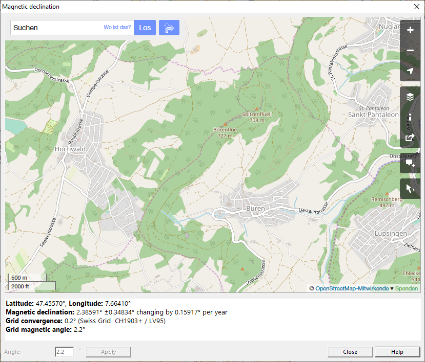
#:Click on '''Magnetic Declination''' to see the current Declination for your position. You can only '''Apply''' the Angle, if no objects have been drawn yet. If you have already drawn objects, use the '''[[Map_Transform#Rotate_Map_to_Magnetic_North|Rotate Map to Magnetic North]]''' function instead. | |||
#:[[File:MagneticDeclination.png]] | |||
# In the '''Grid distance''' field, enter the desired distance for the '''[[View#Show_Screen_Grid|Coordinate Grid]] lines. | # In the '''Grid distance''' field, enter the desired distance for the '''[[View#Show_Screen_Grid|Coordinate Grid]] lines. | ||
[[File:Hint.jpg|hint]] Enter the coordinate values for the center of your map in the horizontal and vertical offset fields. This is important since the drawing area of OCAD is limited to 4 x 4 m in the [[File: | [[File:Hint.jpg|hint]] Enter the coordinate values for the center of your map in the horizontal and vertical offset fields. This is important since the drawing area of OCAD is limited to 4 x 4 m in the [[File:Ori40px.PNG|link=https://www.ocad.com/en/products/ocad-for-orienteering]] '''Orienteering''' edition, in the [[File:Sta40px.PNG|link=https://www.ocad.com/en/products/ocad-for-orienteering]] '''Starter''' edition as well as in the [[File:CS40px.PNG|link=https://www.ocad.com/en/products/ocad-for-orienteering]] '''Course Setting''' edition and 80 x 80 m in the [[File:Mas40px.PNG|link=https://www.ocad.com/en/products/ocad-for-cartography]] '''OCAD Mapping Solution'''. This option is used to ensure that imported '''[[DEM|Spatial Base Data]]''', georeferenced '''[[Background Map|Background Maps]]''' and '''[[GPS]]''' measurements do not lie outside the drawing area. | ||
====Coordinate System==== | ====Coordinate System==== | ||
| Line 56: | Line 57: | ||
*'''EPSG''': The field displays the EPSG-Code (European Petroleum Survey Group Geodesy) of the coordinate system. An external link is provided on the right side of the dialog box. This link refers to '''[http://spatialreference.org/ref/epsg/ spatialreference.org]''', where you can get more information about the chosen coordinate system and zone. | *'''EPSG''': The field displays the EPSG-Code (European Petroleum Survey Group Geodesy) of the coordinate system. An external link is provided on the right side of the dialog box. This link refers to '''[http://spatialreference.org/ref/epsg/ spatialreference.org]''', where you can get more information about the chosen coordinate system and zone. | ||
*'''ID''': The field displays the internal grid ID for this coordinate system. This grid ID is used in the [[[[XML Script#Map|XML Script]]]]. | |||
Click the '''Remove''' button to reset the coordinate system to '''Grid undefined'''.<br /> | Click the '''Remove''' button to reset the coordinate system to '''Grid undefined'''.<br /> | ||
| Line 91: | Line 94: | ||
[[File:Hint.jpg]] Do not use this dialog to change the real world coordinate offset if the map is georeferenced. To move a georeferenced map, use '''Transform''' -> '''[[Map_Transform#Center_Map_to_Drawing_Area|Center Map to Drawing Area]]''' in the '''[[Map]]''' menu and enter the new offset. | [[File:Hint.jpg]] Do not use this dialog to change the real world coordinate offset if the map is georeferenced. To move a georeferenced map, use '''Transform''' -> '''[[Map_Transform#Center_Map_to_Drawing_Area|Center Map to Drawing Area]]''' in the '''[[Map]]''' menu and enter the new offset. | ||
==Next Steps== | |||
Now as you created a new map, you are ready for the next steps. | |||
* Learn how to '''[[Drawing_an_Object|Draw Objects]]'''. | |||
* Learn how to '''[[Edit_Object|Edit Objects]]'''. | |||
* Use Existing Spatial Data: '''[[Import Files]]''', '''[[Database]]''', '''[[WMS]]''', '''[[Background_Map|Background Maps]]'''. | |||
* Processing of LiDAR data and Digital Elevation Models: '''[[DEM_Import_Wizard|DEM Import Wizard]]''', '''[[LiDAR_Point_Cloud_Manager|Lidar Point Cloud Manager]]'''. | |||
* Capture and derive own Data: '''[[GPS]]''', '''[[Laser_Rangefinder|Laser Rangefinder]]'''. | |||
[[File:Hint.jpg]] Check out our tutorials about '''[[O-mapping_with_OCAD|Mapping with OCAD]]'''. | |||
---- | ---- | ||
Back to [[Main Page]] | |||
Back to | |||
Revision as of 08:41, 11 July 2019
OCAD provides predefined symbol sets to help you begin drawing your map immediately.
If you want to import Open Street Map (OSM) data, have a look at the New Map Wizard Page
Create a New Map 


To create a new map:
- Select New in the File menu. The New File dialog box appears.
- Choose a map type. You can now choose a predefined symbol set which fits to your intended map from the selection box. If you want an empty symbol set, choose the Empty symbol set option. Click the Other file button to start with symbols from a different map than those listed. The box lists all symbol files in the \symbol\ sub directory.
 - To add your own set of symbols to the list of predefined symbol sets, simply copy the ocd file to the OCAD sub directory Symbol (usually C:\Program Files\OCAD\OCAD 20xx\Symbol). Symbol files are just normal OCAD maps, usually without any objects. The Map notes box shows information about the specifications of the map.
- - Map notes can be edited in the template file itself. For this purpose choose Map Information in the Map menu.
- - Edit the file OrienteeringMapList.User.txt in the OCAD sub directory Symbol if you want that user defined symbol sets are listed as map type Orienteering map.
- - Do not edit the symbol sets provided by OCAD. When installing a Service Update, OCAD overwrites these symbol sets. So, your changes will be lost. If you want to modify symbols in the symbol set then first save the symbol set with another file name and edit this symbol file.
- - You can add, change or delete symbols in the symbol box at any time.
- Deside in which scale the map shall be drawn. If you change the scale, you can choose also to scale the symbols.
- Choose the language of the symbol set (only at ISOM 2017 available).
- By clicking the OK button, OCAD creates a new map and copies the chosen symbol set to it. You are ready to start!

Set Scale and Coordinate System
Select the Set Scale and Coordinate System item from the Map menu. The Set Scale and Coordinate System dialog box appears.

Map Scale
Enter a scale and click the OK button or adjust the Coordinates settings.
![]() Do not use this dialog to change the scale after entering the initial values. To increase or decrease the size of the map subsequently, use the Change Scale function in the Map menu. Setting the current scale does not enlarge or reduce the map. It only changes a number in the map file and georeferencing will be lost.
Do not use this dialog to change the scale after entering the initial values. To increase or decrease the size of the map subsequently, use the Change Scale function in the Map menu. Setting the current scale does not enlarge or reduce the map. It only changes a number in the map file and georeferencing will be lost.
Georeference the Map
Before loading a georeferenced Background Map, work with GPS data or import Spatial Base Data, we recommend that you first georeference the map. You should contact your data supplier, national surveying office or cartographic institute to find out which coordinate system will best suit your needs.
Coordinates
- Choose wheter you want define Paper coordinates (in mm) or Real world coordinates. Click the corresponding radio button.
- In the Easting offset and Northing offset fields, enter the coordinate values for the center of your map.
- The coordinate system can be rotated by entering a value in the Angle field.
- Click on Magnetic Declination to see the current Declination for your position. You can only Apply the Angle, if no objects have been drawn yet. If you have already drawn objects, use the Rotate Map to Magnetic North function instead.
- In the Grid distance field, enter the desired distance for the Coordinate Grid lines.

![]() Enter the coordinate values for the center of your map in the horizontal and vertical offset fields. This is important since the drawing area of OCAD is limited to 4 x 4 m in the
Enter the coordinate values for the center of your map in the horizontal and vertical offset fields. This is important since the drawing area of OCAD is limited to 4 x 4 m in the ![]() Orienteering edition, in the
Orienteering edition, in the ![]() Starter edition as well as in the
Starter edition as well as in the ![]() Course Setting edition and 80 x 80 m in the
Course Setting edition and 80 x 80 m in the ![]() OCAD Mapping Solution. This option is used to ensure that imported Spatial Base Data, georeferenced Background Maps and GPS measurements do not lie outside the drawing area.
OCAD Mapping Solution. This option is used to ensure that imported Spatial Base Data, georeferenced Background Maps and GPS measurements do not lie outside the drawing area.
Coordinate System
Click the Choose button to define a coordinate system. The Coordinate System dialog appears.

Choose the desired coordinate system. OCAD supports a lot of coordinate systems. The most common one is the UTM (Universal Transverse Mercator) system which is divided into 60 zones limited by meridians and defined worldwide.
- Zone: Depending on the selected coordinate system you must select a zone. If the coordinate system UTM is selected, you can click the Find button to find the correct UTM zone. This function is described in the next paragraph.
- Map datum: This field displays the map datum for the desired coordinate system (Map Datum).
- Ellipsoid: The field displays the ellipsoid from the map datum (Reference Ellipsoid).
- Location: The field displays the location, where the coordinate system can be used.
- EPSG: The field displays the EPSG-Code (European Petroleum Survey Group Geodesy) of the coordinate system. An external link is provided on the right side of the dialog box. This link refers to spatialreference.org, where you can get more information about the chosen coordinate system and zone.
- ID: The field displays the internal grid ID for this coordinate system. This grid ID is used in the [[XML Script]].
Click the Remove button to reset the coordinate system to Grid undefined.
If you are finished, click the OK button.
Find UTM Zone
If UTM is chosen as a coordinate system, the local zone can be found with this tool. Click the Find button next to the Zone dropdown list. The Find UTM Zone dialog appears.

Enter the geographical coordinate (degree of longitude and degree of latitude) of your map.
- Latitude: Enter in this field the degrees of latitude.
- N (North): Click this button if the position is northern of the equator.
- S (South): Click this button if the position is southern of the equator.
- Longitude: Enter in this field the degrees of longitude.
- W (West): Click this button if the position is western of Prime Meridian (London Greenwich).
- E (East): Click this button if the position is eastern of Prime Meridian (London Greenwich).
Click the button OK to calculate the UTM zone. The UTM zone appears in the Coordinate system dialog box.
Example: Coordinate from Baar (Switzerland): 47° 12 North (Latitude), 8° 31' East (Longitude). Enter 47 in the Latitude and 8 in the Longitude field. You will find out that this place is in the UTM zone 32 North.
User Defined Grid
In the Coordinate System dialog you have the option to choose a User Defined Grid in the dropdown list. If you choose it, the dialog box is extended with the Coordinate system parameter part.

You can load the coordinate system from a PRJ-File by clicking the corresponding button. A PRJ-File is a projection format containing coordinate system and projection information. The coordinate system parameter are updated after loading a PRJ-File. Alternatively, the required values can be typed manually but this requires a little experience.
Additional local offset
It is possible to give an additional local offset to the chosen coordinate system. Enter a value for the horizontal and vertical offset in the corresponing fields. This is especially useful if you have to work with GPS very precisely. A tectonic plate can move but the coordinate system stays the same. If you enter a local offset, this problem can be cleared.
Click the OK button to save changes and quit the Set Scale and Coordinate System dialog.
![]() Do not use this dialog to change the real world coordinate offset if the map is georeferenced. To move a georeferenced map, use Transform -> Center Map to Drawing Area in the Map menu and enter the new offset.
Do not use this dialog to change the real world coordinate offset if the map is georeferenced. To move a georeferenced map, use Transform -> Center Map to Drawing Area in the Map menu and enter the new offset.
Next Steps
Now as you created a new map, you are ready for the next steps.
- Learn how to Draw Objects.
- Learn how to Edit Objects.
- Use Existing Spatial Data: Import Files, Database, WMS, Background Maps.
- Processing of LiDAR data and Digital Elevation Models: DEM Import Wizard, Lidar Point Cloud Manager.
- Capture and derive own Data: GPS, Laser Rangefinder.
![]() Check out our tutorials about Mapping with OCAD.
Check out our tutorials about Mapping with OCAD.
Back to Main Page