Example Area Boundary: Difference between revisions
Jump to navigation
Jump to search
No edit summary |
No edit summary |
||
| Line 16: | Line 16: | ||
In the Symbols page: | In the Symbols page: | ||
Set the '''No. of symbols''' to 1 and click the Edit button to the symbol editor. Choose in the symbol editor the '''Point''' type, the '''black''' color and a diameter of '''0.15 mm'''. Then click in the middle of the drawing window to create the point. Click '''Close''' to return to the dialog. | Set the '''No. of symbols''' to 1 and click the Edit button to go to the symbol editor. Choose in the symbol editor the '''Point''' type, the '''black''' color and a diameter of '''0.15 mm'''. Then click in the middle of the drawing window to create the point. Click '''Close''' to return to the dialog. | ||
[[File:AreaBoundary_SymbolEditor.PNG]][[File:AreaBoundary_SymbolEditor_02.PNG]] | [[File:AreaBoundary_SymbolEditor.PNG]][[File:AreaBoundary_SymbolEditor_02.PNG]] | ||
Latest revision as of 11:02, 11 September 2013
To create this symbol, start from an empty line symbol and then do the following steps:
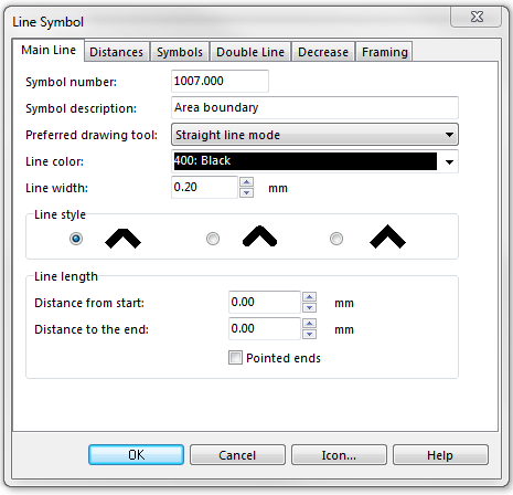
In the Main Line page:
- Enter Line color and Line width.
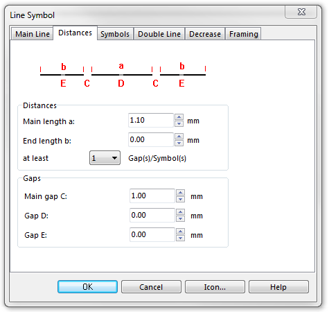
In the Distances page:
- Enter the dash length of the center line in Main length a.
- Enter the length of the gap in the center line in Main gap C.
In the Symbols page:
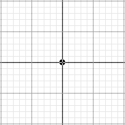
Set the No. of symbols to 1 and click the Edit button to go to the symbol editor. Choose in the symbol editor the Point type, the black color and a diameter of 0.15 mm. Then click in the middle of the drawing window to create the point. Click Close to return to the dialog.
Download link: [Example_AreaBoundary.ocd]
Back to Create a New Symbol


