|
|
| Line 11: |
Line 11: |
|
| |
|
| ==Create a New Area Symbol [[File:Space.PNG]][[File:Pro40px.PNG|This function is available in OCAD 11 Professional.|link=https://www.ocad.com/en/products/ocad-for-cartography]][[File:Std40px.PNG|This function is available in OCAD 11 Orienteering Standard.|link=https://www.ocad.com/en/products/ocad-for-orienteering]][[File:Sta40px.PNG|This function is available in OCAD 11 Starter.|link=https://www.ocad.com/en/products/ocad-for-orienteering]][[File:CS40px.PNG|This function is available in OCAD 11 Course Setting.|link=https://www.ocad.com/en/products/ocad-for-orienteering]]== | | ==Create a New Area Symbol [[File:Space.PNG]][[File:Pro40px.PNG|This function is available in OCAD 11 Professional.|link=https://www.ocad.com/en/products/ocad-for-cartography]][[File:Std40px.PNG|This function is available in OCAD 11 Orienteering Standard.|link=https://www.ocad.com/en/products/ocad-for-orienteering]][[File:Sta40px.PNG|This function is available in OCAD 11 Starter.|link=https://www.ocad.com/en/products/ocad-for-orienteering]][[File:CS40px.PNG|This function is available in OCAD 11 Course Setting.|link=https://www.ocad.com/en/products/ocad-for-orienteering]]== |
| | | Visit the '''[[Create a New Area Symbol]]''' page to learn more about this function. |
| [[File:AreaSymbol.JPG|miniatur|350x350px|right|new area symbol]]
| |
| | |
| You can create area symbols with OCAD. In addition to the following options, the symbol editor can make use of all the drawing modes and editing tools that are available for objects in the normal drawing window:
| |
| * '''General:''' Used to define the color and the borderline.
| |
| * '''Hatch:''' Used to define the line thickness, distance and orientation of the hatching.
| |
| * '''Structure:''' Used to define the structure symbol as well as the distances and orientation of the structure.
| |
| | |
| # Select '''New''' in the '''Symbol''' menu.
| |
| # Select the symbol type '''Area Symbol'''. The '''Area Symbol''' dialog box appears.
| |
| # Enter a number between 0.001 and 999999.999 in the '''Symbol number''' field and a symbol description in the '''Description''' field.
| |
| # Click '''Edit'''. The symbol editor appears.
| |
| # If required, configure the options 'general', 'hatch' and 'structure' for the area symbol.
| |
| # Once you have defined the area symbol, select '''Icon''' in the dialog window. The '''Edit Icon''' dialog window appears.
| |
| # Draw the icon in the 22 x 22 pixel matrix field using the various drawing tools.
| |
| # When you are finished, click '''OK''' twice. The new symbol appears in the symbol field.
| |
| | |
| [[File:Camera.jpg|video available]] [http://www.ocad.com/howtos/61.htm Different area symbols]
| |
| | |
| | |
| | |
| '''Define the structure of the area'''
| |
| * '''Structure:''' Choose None if you want no structure or choose one of the two layouts for the structure.
| |
| * '''Width:''' Enter the horizontal distance from one structure to the next (center to center). This distance is horizontal if the angle is 0, otherwise it is measured in the corresponding angle.
| |
| * '''Height:''' Enter the vertical distance from one structure line to the next (center to center). This distance is vertical if the angle is 0, otherwise it is measured in the corresponding angle.
| |
| * '''Angle:''' Enter here the angle of the structure. If this angle is 0 the structure is drawn as shown in the Structure box. Otherwise it is rotated counterclockwise for positive angles.
| |
| * '''Edit:''' Click this button to draw one structure element in the symbol editor. In the symbol editor the symbol will also appear (in gray) in the position of the neighboring structures in order to get an impression of the structured area. If you enter an angle other than 0, the structure will be rotated, but not the symbol.
| |
| : '''Remark:''' It is possible to rotate the structure of individual objects drawn with that symbol with the '''Indicate Direction of Area Pattern, Point or Text Object''' button. In this case the structure and the structure symbols will be rotated.
| |
| | |
| | |
| '''Define Parameters for a hatched area'''
| |
| * '''Hatch:''' Choose None if you do not want a hatch; or choose a simple hatch or a cross-hatch.
| |
| * '''Color:''' Choose a color for the hatch lines.
| |
| * '''Line width:''' Enter the line width for the hatch lines.
| |
| * '''Distance:''' Enter the distance between the hatch lines.
| |
| * '''Angle 1:''' Enter the angle for the hatch lines. 0 means horizontal lines. For angles greater than 0, the lines are rotated counterclockwise.
| |
| * '''Angle 2:''' Enter the second angle for the hatch lines if you have defined a cross-hatch. Otherwise this value is ignored. 0 means horizontal lines. For angles greater than 0, the lines are rotated counterclockwise.
| |
| | |
| : [[File:Example.jpg|example]] [[Example Boulders with shrubbery]]
| |
| : [[File:Example.jpg|example]] [[Example Dam]]
| |
| | |
|
| |
|
| ==Create a New Text Symbol [[File:Space.PNG]][[File:Pro40px.PNG|This function is available in OCAD 11 Professional.|link=https://www.ocad.com/en/products/ocad-for-cartography]][[File:Std40px.PNG|This function is available in OCAD 11 Orienteering Standard.|link=https://www.ocad.com/en/products/ocad-for-orienteering]][[File:Sta40px.PNG|This function is available in OCAD 11 Starter.|link=https://www.ocad.com/en/products/ocad-for-orienteering]][[File:CS40px.PNG|This function is available in OCAD 11 Course Setting.|link=https://www.ocad.com/en/products/ocad-for-orienteering]]== | | ==Create a New Text Symbol [[File:Space.PNG]][[File:Pro40px.PNG|This function is available in OCAD 11 Professional.|link=https://www.ocad.com/en/products/ocad-for-cartography]][[File:Std40px.PNG|This function is available in OCAD 11 Orienteering Standard.|link=https://www.ocad.com/en/products/ocad-for-orienteering]][[File:Sta40px.PNG|This function is available in OCAD 11 Starter.|link=https://www.ocad.com/en/products/ocad-for-orienteering]][[File:CS40px.PNG|This function is available in OCAD 11 Course Setting.|link=https://www.ocad.com/en/products/ocad-for-orienteering]]== |
| | | Visit the '''[[Create a New Text Symbol]]''' page to learn more about this function. |
| [[File:TextSymbol.JPG|miniatur|350x350px|right|new text symbol]]
| |
| | |
| You can create text symbols with OCAD. The following options are available:
| |
| * '''General:''' Used to define the font color, type and size.
| |
| * '''Paragraph:''' Used to define the paragraph attributes
| |
| * '''Tabulator:''' Used to define the tab attributes
| |
| * '''Line Below:''' Used to define the underscore attributes
| |
| * '''Framing:''' Used to define the framing and combination with point symbols
| |
| | |
| # Select '''New''' in the '''Symbol''' menu.
| |
| # Select the symbol type '''Text Symbol'''. The Text Symbol dialog box appears.
| |
| # Enter a number between 0.001 and 999999.999 in the '''Symbol number''' field and a symbol description in the '''Description'''field.
| |
| # Click '''Edit'''. The symbol editor appears.
| |
| # If required, configure the options 'general', 'paragraph', 'tabulator', 'line below' and 'framing' for the text symbol.
| |
| # Once you have defined the '''Text Symbol''', select '''Icon''' in the dialog window. The '''Edit Icon''' dialog window appears.
| |
| # Draw the icon in the 22 x 22 pixel matrix field using the various drawing tools.
| |
| # When you are finished, click '''OK''' twice. The new symbol appears in the symbol field.
| |
| | |
| | |
| [[File:Camera.jpg|video available]] [http://www.ocad.com/howtos/62.htm Different text symbols]
| |
| | |
| [[File:Hint.jpg|hint]] For every text style, a separate symbol is required. If you modify the text symbol, then all text written with that symbol will change. See also Symbols (basic principles).
| |
| [[File:Hint.jpg|hint]] The error message: "Font not found" appears if a font is chosen that is not installed on the PC. The font needs to be installed on the PC or another font must be chosen. Otherwise the font Arial is used.
| |
| | |
| | |
| '''General'''
| |
| | |
| Choose this page to define general text symbol parameters.
| |
| * '''Symbol no.:''' Enter here a number between 0.001 and 999,999.999 for the symbol. Each symbol in a given map requires a unique number.
| |
| * '''Description:''' Enter here a description for the symbol. The description is displayed when selecting the symbol or when selecting an object with that symbol.
| |
| * '''TrueType Font:''' Choose a font for the text symbol. All TrueType fonts installed in Windows are listed. You cannot use raster fonts or Adobe Type Manager fonts.
| |
| * '''Color:''' Choose the color for the text.
| |
| * '''Size:''' Choose the size in points for the text. As an alternative you can enter the character height in millimeters in the box '''Character height'''.
| |
| * '''Character height:''' Enter here the height of the character 'B' in millimeters. Alternatively you can enter the size of the font in points in the box '''Size'''.
| |
| * '''Bold:''' Check this box for bold text.
| |
| * '''Italic:''' Check this box for italic text.
| |
| | |
| * '''Drawing mode'''
| |
| This setting is used if you rotate the map with the command '''Rotate Map''' in the menu '''Map'''.
| |
| : Horizontal text: Choose this option if the text shall be rendered horizontal after a rotation of the map.
| |
| : Rotated text: Choose this option if the text shall rotate with the map after a rotation of the map.
| |
| | |
| * '''Course setting symbol'''
| |
| : ''(This function is only available in course setting projects!)''
| |
| : Activate this option if the symbol is used for course titles or start numbers for relay courses.
| |
| | |
| | |
| '''Paragraph'''
| |
| | |
| Choose this page to define parameters for text paragraphs.
| |
| * '''Char. spacing:''' Enter here a distance to be inserted between characters. If you enter 100% a space character is inserted between characters. Default value is 0%.
| |
| * '''Word spacing:''' Enter here the distance between words. 100% means that a normal space character is used between words. Default value is 100%.
| |
| * '''Alignment:''' Choose the alignment of the text.
| |
| * '''Line spacing:''' Enter the distance from one line to the next within a paragraph, in relation to the font size. Standard value is 120%.
| |
| * '''Space after paragraph:''' Enter the additional space after each paragraph.
| |
| * '''Indent first:''' Enter the indent of the first line of each paragraph.
| |
| * '''Indent other lines:''' Enter the indent of the other lines of each paragraph.
| |
| | |
| | |
| '''Tab'''
| |
| | |
| Choose this page to set the tabs for the text symbol. The tabs are left adjusted. A maximum of 32 tabs can be defined. If a text contains more tab characters than defined in the list, the distance to the last tab is repeated.
| |
| * ''' To add a new tab:''' Enter the position and click Add. The tab is added to the list.
| |
| * ''' To delete a tab:''' Click on the tab to be deleted on the list. Then click Delete.
| |
| | |
| | |
| '''Line Below'''
| |
| | |
| Choose this page to define a line which is drawn below each paragraph. (A paragraph is terminated by a hard return - the '''Enter''' key.)
| |
| * '''On:''' Check this box to get a line below the paragraphs.
| |
| * '''Line color:''' Choose a color for the line.
| |
| * '''Line width:''' Enter a line width.
| |
| * '''Distance from text:''' Enter a distance from the baseline of the text to the upper edge of the line.
| |
| | |
| | |
| '''Framing'''
| |
| | |
| Choose this page to set the parameters for text framing.
| |
| * '''Off:''' Activate this box if you don't want to use text framing.
| |
| * '''Line:''' Enter here the width (how much the framing extends outside the character) of the text framing.
| |
| * '''Shadow:''' Choose this option if a shadow to the text shall be rendered. Enter the horizontal and vertical offset of the shadow. Choose the color.
| |
| * '''Rectangle:''' Choose this option to add a rectangular background. Enter the values Left, Right, Bottom and Top if the rectangle shall overlap the text. Choose a color.
| |
| * '''Color::''' Choose a color. To get text framing, this color must be below the color of the main font in the color table, but above the colors of any objects which you wish to cover.
| |
| * '''Point symbol:''' Check On if you want to attach a point symbol to the text symbol. Choose a point symbol.
| |
| | |
| | |
| Text framing is a method to make text more readable on maps. If - for instance - you have black text on a map, it may interfere with black line objects. Text framing can also be used for decorative effects - giving the text a shadow, for instance.
| |
| | |
| [[File:TxtWithout.PNG|without frame]] [[File:TxtFrame.PNG|framed text.]]
| |
|
| |
| For text framing you need to understand the '''color table''' and you should have some experience in creating new colors and new symbols.
| |
|
| |
| First you need two additional colors which are above the black color for symbols:
| |
| | |
| [[File:Framecol.gif|color table from text framing]]
| |
| | |
| Then you can add text framing to an existing text symbol:
| |
| # Right click the text symbol and choose '''Edit''' from the context menu.
| |
| # Choose the '''General page'''. Choose "Black for text" for the text color.
| |
| # Choose the '''Framing''' page. Activate '''Line'''.
| |
| # Enter the desired framing width.
| |
| # Choose "White for text frames" in the Color box.
| |
| | |
| | |
| '''Selective text framing'''
| |
| | |
| Often text framing erases only the black color, but the other colors still come through. OCAD allows selective text framing for printing the map with spot colors (PMS or Pantone colors), by defining the appropriate spot colors. However, on the screen all colors below the framing color are erased. So beware: the appearance of the map on the screen and the printed map will be different.
| |
| Selective text framing is also possible for CMYK printing. For this case you have to define your own "spot colors" for CMYK. You cannot use the automatic CMYK color separations.
| |
| | |
| | |
| Choose this page to set the parameters for '''text framing'''.
| |
| * '''Off:''' Activate this box if you want to use text framing.
| |
| * '''Line:''' Enter here the width (how much the framing extends outside the character) of the text framing.
| |
| * '''Shadow:''' Choose this option if a shadow to the text shall be rendered. Enter the horizontal and vertical offset of the shadow. Choose a color.
| |
| * '''Color:''' Choose a color. To get text framing, this color must be below the color of the main font in the color table, but above the colors of any objects which you wish to cover.
| |
|
| |
|
| ==Create a New Line Text Symbol [[File:Space.PNG]][[File:Pro40px.PNG|This function is available in OCAD 11 Professional.|link=https://www.ocad.com/en/products/ocad-for-cartography]][[File:Std40px.PNG|This function is available in OCAD 11 Orienteering Standard.|link=https://www.ocad.com/en/products/ocad-for-orienteering]][[File:Sta40px.PNG|This function is available in OCAD 11 Starter.|link=https://www.ocad.com/en/products/ocad-for-orienteering]][[File:CS40px.PNG|This function is available in OCAD 11 Course Setting.|link=https://www.ocad.com/en/products/ocad-for-orienteering]]== | | ==Create a New Line Text Symbol [[File:Space.PNG]][[File:Pro40px.PNG|This function is available in OCAD 11 Professional.|link=https://www.ocad.com/en/products/ocad-for-cartography]][[File:Std40px.PNG|This function is available in OCAD 11 Orienteering Standard.|link=https://www.ocad.com/en/products/ocad-for-orienteering]][[File:Sta40px.PNG|This function is available in OCAD 11 Starter.|link=https://www.ocad.com/en/products/ocad-for-orienteering]][[File:CS40px.PNG|This function is available in OCAD 11 Course Setting.|link=https://www.ocad.com/en/products/ocad-for-orienteering]]== |
| | | Visit the '''[[Create a New Line Text Symbol]]''' page to learn more about this function. |
| [[File:LineTextSymbol.JPG|miniatur|350x350px|right|new line text symbol]]
| |
| | |
| You can create line text symbols with OCAD. The following options are available:
| |
| * '''General:''' Used to define the font color, type and size.
| |
| * '''Spacing:''' Used to define the letters, word spacing and text positioning.
| |
| * '''Framing:''' Used to define the framing
| |
| | |
| # Select '''New''' in the '''Symbol''' menu.
| |
| # Select the symbol type '''Line Text''' Symbol. The Line Text Symbol dialog box appears.
| |
| # Enter a number between 0.001 and 999999.999 in the Symbol number field and a symbol description in the Description field.
| |
| # Click '''Edit'''. The symbol editor appears.
| |
| # If required, configure the options 'general', 'spacing' and 'framing' for the text line symbol.
| |
| # Once you have defined the line text symbol, select Icon in the dialog window. The Edit Icon dialog window appears.
| |
| # Draw the icon in the 22 x 22 pixel matrix field using the various drawing tools.
| |
| # When you are finished, click '''OK''' twice. The new symbol appears in the symbol field.
| |
| | |
| | |
| '''General'''
| |
| | |
| * '''Preferred tool:''' Choose here a drawing mode. Each time the symbol is selected, the drawing mode changes to this drawing mode. Choose None to switch off this feature.
| |
| * '''TrueType Font:''' Choose a font for the text symbol. All TrueType fonts installed in Windows are listed. You cannot use raster fonts or Adobe Type Manager fonts.
| |
| * '''Color:''' Choose the color for the text.
| |
| * '''Size:''' Choose the size in points for the text. Alternatively, you can enter the character height in millimeters in the box Character height.
| |
| * '''Character height:''' Enter here the height of the character 'B' in millimeters. Alternatively you can enter the size of the font in points in the box Size.
| |
| * '''Bold:''' Check this box for bold text.
| |
| * '''Italic:''' Check this box for italic text.
| |
| | |
| [[File:Hint.jpg|hint]] The error message: "Font not found" appears if a font is chosen that is not installed on the PC. The font needs to be installed on the PC or another font must be chosen. Otherwise the font Arial is used.
| |
| | |
| | |
| Line text symbols are used for text along curved lines.
| |
| Line text can be written along any line, including curved lines. To draw a line text object you must define a '''line text symbol''' and then:
| |
| # Select the line text symbol
| |
| # Draw a line in any drawing mode (curve, ellipse, circle etc.)
| |
| # After terminating the line, an insertion line appears and you can directly type the text on the keyboard.
| |
| # If the text goes in the wrong direction, click the '''Reverse line''' button.
| |
| | |
| | |
| '''Spacing''' | |
| Choose this page to define spacing and alignment for a '''line text''' symbol.
| |
| * '''Character spacing:''' Enter here a distance to be inserted between characters. If you enter 100% a space character is inserted between characters.
| |
| * '''Word spacing:''' Enter here the distance between words. 100% means that a normal space character is used between words.
| |
| * '''Alignment:''' Choose here how the text is aligned along the line. '''All line''' means that the text is distributed along the entire line. With this option the ''letter-spacing'' will be adapted to the length of the line text object.
| |
|
| |
|
| ==Create a New Rectangle Symbol [[File:Space.PNG]][[File:Pro40px.PNG|This function is available in OCAD 11 Professional.|link=https://www.ocad.com/en/products/ocad-for-cartography]][[File:Std40px.PNG|This function is available in OCAD 11 Orienteering Standard.|link=https://www.ocad.com/en/products/ocad-for-orienteering]][[File:Sta40px.PNG|This function is available in OCAD 11 Starter.|link=https://www.ocad.com/en/products/ocad-for-orienteering]][[File:CS40px.PNG|This function is available in OCAD 11 Course Setting.|link=https://www.ocad.com/en/products/ocad-for-orienteering]]== | | ==Create a New Rectangle Symbol [[File:Space.PNG]][[File:Pro40px.PNG|This function is available in OCAD 11 Professional.|link=https://www.ocad.com/en/products/ocad-for-cartography]][[File:Std40px.PNG|This function is available in OCAD 11 Orienteering Standard.|link=https://www.ocad.com/en/products/ocad-for-orienteering]][[File:Sta40px.PNG|This function is available in OCAD 11 Starter.|link=https://www.ocad.com/en/products/ocad-for-orienteering]][[File:CS40px.PNG|This function is available in OCAD 11 Course Setting.|link=https://www.ocad.com/en/products/ocad-for-orienteering]]== |
| [[File:RectangleSymbol.JPG|miniatur|350x350px|right|new rectangle symbol]]
| | Visit the '''[[Create a Rectangle Symbol]]''' page to learn more about this function. |
| | |
| You can create rectangle symbols with OCAD.
| |
| | |
| # Select '''New''' in the '''Symbol''' menu.
| |
| # Select the symbol type '''Rectangle''' Symbol. The Rectangle symbol dialog box appears.
| |
| # Enter a number between 0.001 and 999999.999 in the '''Symbol no.''' field and a symbol description in the '''Description''' field.
| |
| # Choose a '''Line color''' and '''Line width''', a '''Drawing mode''' and set the '''Grid''' and '''Numbering''' options.
| |
| # Once you have defined the rectangle symbol, click '''Icon''' to open the '''Edit Icon''' dialog box.
| |
| # Draw the icon in the 22 x 22 pixel matrix field using the various drawing tools.
| |
| # When you are finished, click '''OK''' twice. The new symbol appears in the symbol box.
| |
| | |
| | |
| '''Rectangle symbols'''
| |
| Rectangle symbols are used to draw rectangular frames (around the entire map or around parts of the map). A special use for Rectangle symbols is punch boxes for orienteering maps. | |
| * '''Symbol no.:''' Enter here a number between 0.001 and 999'999.999 for the symbol. Each symbol requires a unique number.
| |
| * '''Description:''' Enter here a description for the symbol. The description is displayed when selecting the symbol or when selecting an object with that symbol.
| |
| * '''Line Color:''' Choose a color for the frame.
| |
| * '''Line width:''' Enter a line width for the frame.
| |
| * '''Corner radius:''' If you want the frame to have round corners, enter the corner radius here (measured to the center of the line), otherwise enter 0 here.
| |
| | |
| | |
| '''Drawing mode'''
| |
| * '''Horizontal rectangle:''' Activate this option if you want to draw only horizontal rectangles.
| |
| * '''Rotated rectangle:''' Activate this option if you want to draw rotate rectangles.
| |
| | |
| | |
| '''Grid'''
| |
| * '''On:''' Activate this field if you want to draw punch boxes for orienteering maps.
| |
| * '''Cell width / Cell height:''' Enter the desired width and height for the cells.
| |
| | |
| | |
| '''Numbering'''
| |
| * '''On:''' Activate this field if you want numbers for the grid.
| |
| * '''Numbered from the bottom:''' Normally the cells are numbered starting from the top row. Check this box to start numbering from the bottom row.
| |
| * '''Text size:''' Choose the size in points for the text.
| |
| * '''Unnumbered Cells'''
| |
| : '''Number:''' Enter here the number of cells used as reserved fields.
| |
| : '''Text:''' Enter here up to 3 characters which appear instead of the number in the reserved fields. If you want all cells numbered enter here 0.
| |
| | |
|
| |
|
| ==Icon Editor [[File:Space.PNG]][[File:Pro40px.PNG|This function is available in OCAD 11 Professional.|link=https://www.ocad.com/en/products/ocad-for-cartography]][[File:Std40px.PNG|This function is available in OCAD 11 Orienteering Standard.|link=https://www.ocad.com/en/products/ocad-for-orienteering]][[File:Sta40px.PNG|This function is available in OCAD 11 Starter.|link=https://www.ocad.com/en/products/ocad-for-orienteering]][[File:CS40px.PNG|This function is available in OCAD 11 Course Setting.|link=https://www.ocad.com/en/products/ocad-for-orienteering]]== | | ==Icon Editor [[File:Space.PNG]][[File:Pro40px.PNG|This function is available in OCAD 11 Professional.|link=https://www.ocad.com/en/products/ocad-for-cartography]][[File:Std40px.PNG|This function is available in OCAD 11 Orienteering Standard.|link=https://www.ocad.com/en/products/ocad-for-orienteering]][[File:Sta40px.PNG|This function is available in OCAD 11 Starter.|link=https://www.ocad.com/en/products/ocad-for-orienteering]][[File:CS40px.PNG|This function is available in OCAD 11 Course Setting.|link=https://www.ocad.com/en/products/ocad-for-orienteering]]== |
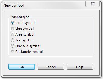
New symbols can be created by choosing New in the Symbol menu. The New Symbol dialog box appears. Select one of the six different symbol types.
Create a New Point Symbol 


Visit the Create a New Point Symbol page to learn more about this function.
Create a New Line Symbol
Visit the Create a New Line Symbol page to learn more about this function.
Create a New Area Symbol
Visit the Create a New Area Symbol page to learn more about this function.
Create a New Text Symbol
Visit the Create a New Text Symbol page to learn more about this function.
Create a New Line Text Symbol
Visit the Create a New Line Text Symbol page to learn more about this function.
Create a New Rectangle Symbol
Visit the Create a Rectangle Symbol page to learn more about this function.
Icon Editor
Choose the Icon command in the Symbol menu to edit the icon of the selected symbol. Alternatively, you can click the symbol in the symbol box with the right mouse button and choose the Icon command. The Icon Editor dialog box appears.
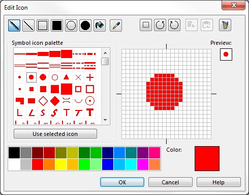
Draw the icon in the 22x22 matrix. You can use different drawing tools:
 Pen: Draw single pixels
 Line: Draw a straight line
 Rectangle: Draw a rectangle
 Filled Rectangle: Draw a filled rectangle
 Ellipse: Draw an ellipse
 Filled Circle: Draw a filled ellipse
 Fill: Fill an area (bordering pixels with the same color) with the selected color.
Before drawing choose one of the 26 colors.
Alternatively, you can choose a predefined icon from the Symbol icon palette. Select an icon and click the Use selected icon button to overwrite the current one.
You can use the following editing tools:
 Pick Color: Pick a color from the 22x22 drawing area
 Select: With this tool you can select some pixels. After the selection you can move them or copy and paste them.
 Rotate Counterclockwise: Rotate the whole icon counterclockwise
 Rotate Clockwise: Rotate the whole icon clockwise
 Copy: Copy a selection of pixels
 Paste: Paste a selection of pixels
 Open Paint: This button opens the Paint application of Windows. You can draw an icon in Paint. Make sure, your Paint document has the dimensions 22x22 pixels to get a satisfying result. When you are finished with drawing, select and copy the icon. Now you can paste it in the Icon Editor of OCAD.
 There is an easy way to get an icon for a point object. Simply use the Make screenshot for symbol icon function in the Symbol Editor.
Define a New Color 
When displaying maps, OCAD uses the colors in the color table in a specific order; objects which use the lowest colors in the table are drawn first, objects which use the colors at the top of the table are drawn last. The advantage of this technique is that lines or areas can be omitted automatically. This is especially beneficial when drawing road junctions (cf. below).
- Select New in the File menu.
- In the New Map dialog window, double-click empty Symbolset.ocd.
- To edit the color table, select Colors in the Map menu.
- To create a new color, select Add in the color table and enter the name (e.g. pictogram white foreground) and CMYK value (e.g. blue 0/0/0/0) of the color.
- You can change the position of the colors in the color table by clicking the Move up and Move down buttons.
 Color table
Color basics
Roads are often displayed using two lines with a color filling between these lines. If two roads intersect, the side lines in the area where the roads cross each other must be omitted.
If two roads intersect at an under or overpass, only the lines of the lower road should be omitted. By moving the position of the color upwards or downwards, you will be able to influence these effects:
- Intersections: If the color of the filling is located above the color of the side lines in the color table, the side lines in the area where the roads cross each other will be omitted automatically.
- Overpass: To ensure the side lines are not omitted automatically, a new color must be defined for the side lines of the overpass. This color must be located above the filling color in the color table.

Selecting Symbols in Symbol Box
To select one symbol, click the desired symbol.
To select a consecutive group of symbols:
- Click the first symbol.
- Press and hold down the Shift key on the keyboard and click the last symbol.
To select a non-consecutive group of symbols:
- Click the first symbol.
- Press and hold down the Ctrl key on the keyboard and click all the additional symbols.
Preferences
Default symbol folder: Set the default symbol folder here. When a new file is created the symbol sets available in the New Map dialog box are loaded from this folder.
Symbol box:
- Selected symbol blink: If this option is activated the icon border of the selected symbol in the symbol box is blinking.
- Lock symbol position: If this option is activated it is not possible to move symbols with drag and drop in the symbol box
- Auto select symbol when selecting object: If this option is activated and you select an object on the drawing area, the corresponding symbol is automatically selected.
If you would like to assign a color which does not yet exist, to the new symbol, a new color will need to be defined.
Each symbol must have a unique symbol number between 0.001 and 999999.999.
Previous Chapter: Colors
Next Chapter: Background Map
Back to Main Page


