Create a New Area Symbol
You can create quite complex area symbols with OCAD. In addition, the symbol editor can make use of nearly all the drawing modes and editing tools that are available for objects in the normal drawing window to make an area symbol even more unique.
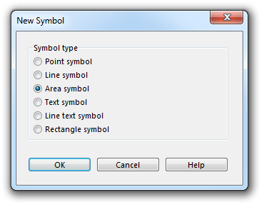
Choose the New command in the Symbol menu. Then, choose the Area Symbol option in the New Symbol dialog to create a new area symbol.
The Area Symbol dialog appears. This dialog provides the following three tabs:
- General: Used to define the color and the borderline.
- Hatch: Used to define the line thickness, distance and orientation of the hatching.
- Structure: Used to define the structure symbol as well as the distances and orientation of the structure.
General
In this tab you can make general adjustments like those for the fill and borderlines.
Symbol Number
Type a symbol number between 0.001 and 999999.999 in this field.
Symbol Description
Enter a symbol description in this field (e.g. Lake).
Preferred Drawing Tool
Choose a preferred drawing tool in the corresponding dropdown list. When the symbol is selected in the Symbol Box the drawing mode changes automatically to the chosen one. If None was chosen, the drawing mode remains the same as it was before.
Fill
Check the On field to activate the fill. Allocate a fill color from the dropdown list. All colors from the Color Table appear in this dropdown list. If you use borderlines or a structure, make sure that the fill color is below the borderline respectively the structure color in the Color Table. Otherwise, the fill covers the structure completely or the borderline is only shown with half the width.
Border
Activate borderlines by checking the corresponding On checkbox. Then, select a line symbol in the dropdown list below. All line symbols in the Symbol Box are listed there. Make sure that the color of the line symbol is above the color of the fill in the Color Table, otherwise half of the line symbol will be covered by it.
Orientation to North
Check the Hatch/Structure orientated to north when rotating the map option if you want to keep a hatch or structure always orientated to north when rotating the map (Rotate).
Hatch
In this tab you can define the parameters for a simple hatch or a cross-hatch.
Hatch
Choose between None if you do not want a hatch, simple hatch or a cross-hatch.
Color
Choose a color for the hatch lines. Make sure that this color is above the background color of the area in the Color Table.
Line Width
Enter a line width in mm for the hatch lines in this field.
Distance
Enter the distance between the hatch lines in this field.
Angles
- Angle 1: Enter the angle for the hatch lines. 0 means that the lines are horizontal. For angles greater than 0, the lines are rotated counterclockwise.
- Angle 2: Enter the second angle for the hatch lines if you have defined a cross-hatch. Otherwise this value is ignored. 0 means that the lines are horizontal. For angles greater than 0, the lines are rotated counterclockwise.
Structure
In this tab you can define the parameters for a structure.
Structure
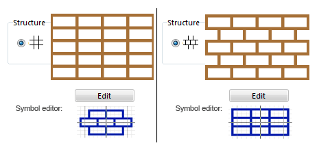
Choose between None if you do not want a structure or one of the two layouts for structures.
Width
Enter the horizontal distance from one structure to the next (center to center). This distance is horizontal if the angle is 0, otherwise it is measured in the corresponding angle.
Height
Enter the vertical distance from one structure line to the next (center to center). This distance is vertical if the angle is 0, otherwise it is measured in the corresponding angle.
Angle
Enter here the angle of the structure. If this angle is 0 the structure is drawn as shown in the structure box. Otherwise it is rotated counterclockwise for positive angles.
Edit
Click this button to draw one structure element in the Symbol Editor. In the Symbol Editor the symbol will also appear (in gray) in the position of the neighboring structures in order to get an impression of the structured area. If you enter an angle other than 0, the structure will be rotated, but not the symbol. Read more about the Symbol Editor in the Symbol Editor article. This article contains also a paragraph for structured areas.
![]() It is possible to rotate the structure of individual objects drawn with that symbol with the Indicate Direction of Area Pattern, Point or Text Object button. In this case the structure and the structure symbols will be rotated.
It is possible to rotate the structure of individual objects drawn with that symbol with the Indicate Direction of Area Pattern, Point or Text Object button. In this case the structure and the structure symbols will be rotated.
Examples
![]() Example Boulders with Shrubbery
Example Boulders with Shrubbery
- This is an example for a structured area symbol.
- This is an example for a structured area symbol.
Icon
Click the Icon button in the dialog to create an icon for the symbol. The Icon Editor appears. Read more about this editor in the Icon Editor article.
Back to the Create a New Symbol page.


