Topologie
The Topology submenu can be found in the Object menu.
Anpassen 


Choose the ![]() Join function in the Topology submenu of the Object menu or in the Edit Functions Toolbar.
This function is active if a line object is selected.
Join function in the Topology submenu of the Object menu or in the Edit Functions Toolbar.
This function is active if a line object is selected.
Use this function to adjust adjoining line ends so that they coincide. Only line objects with the same symbol are joined. This is especially useful when continuing a line object such as a contour. Note that the objects remain independent objects, but the coordinates of the end vertices are equalized. If you want to merge objects, choose the Verschmelzen command.
Automatisches Anpassen
If you enable ![]() Automatic Joining in the Edit Functions Toolbar, end points of lines are joined automatically when finishing drawing a line near another line end. The Join when drawing lines tolerance can be set in the Zeichnen und Editieren category of the OCAD Präferenzen. To switch off the automatic joining temporary during drawing, press the Shift key when terminating the line.
Automatic Joining in the Edit Functions Toolbar, end points of lines are joined automatically when finishing drawing a line near another line end. The Join when drawing lines tolerance can be set in the Zeichnen und Editieren category of the OCAD Präferenzen. To switch off the automatic joining temporary during drawing, press the Shift key when terminating the line.
Toleranz
Define how close two line end points have to be for joining them in the Zeichnen und Editieren category of OCAD Präferenzen.
Duplikate selektieren
Choose this function from the Topology submenu of the Object menu.
With this function you can find all duplicate objects. The objects must be identical and on the same position that they can be found.
![]() Objects with different symbols whose geometry is identical are not selected.
Objects with different symbols whose geometry is identical are not selected.
Selbst überschneidende Objekte selektieren
Choose this function from the Topology submenu of the Object menu.
This function selects all line, area and line text objects with a self-intersecting geometry. The selection can be saved right after carrying out the command (Selektion speichern).
Linientext-Objekte mit zu kurzen Linien selektieren
Choose this function from the Topology submenu of the Object menu.
This function selects all line text objects whose text is longer than the line length. This can happen when the font of a text symbol has been increased. The selection can be saved right after carrying out the command (Selektion speichern).
Linientext-Objekte verlängern
Wählen Sie diese Funktion aus dem Untermenü Topologie des Menüs Objekt.
Die Funktion verlängert die selektierten Linientext-Objekte um eine angegebene Länge oder einen Prozentwert der bestehenden Länge. Die Verlängerung wird immer am Ende des Linientext-Objekts angehängt. Wählen Sie die Option Verlängern um Distanz oder Verlängern in Prozent der aktuellen Länge und geben Sie die Distanz in mm oder den Prozentwert ein.

Objekte mit ungültiger Geometrie selektieren
Choose this function from the Topology submenu of the Object menu to select all objects with invalid geometry.
The following objects are selected:
- Objects which start with a hole: OCAD selects all objects, whose first vertex has a hole flag. This can be a hole with no exterior ring.
- Damaged Bezier curves: A Bezier curve is composed of minimum a start point, a first Bezier vertex, a second Bezier vertex and an end point (see illustration).
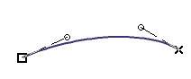
- If a Bezier curve has less than these vertices, it is selected.

- Line objects with invalid hole flag: A line object which contains a vertex with a hole flag is selected.
- Area object with invalid geometry: OCAD selects all area objects, whose vertices have the same coordinate. This problem can occur when the scale is reduced.
- Line objects with the same start and end point: This problem can occur when the scale is reduced. In this case, the start and end point of a really short line object can fall together.
- Area object with an invalid hole: A hole must have minimum three vertices. A hole with one or two vertices is selected (see illustration).

- Area object with an invalid exterior ring: An invalid exterior ring can be a ring with only one vertex (see illustration).

- Graphic object with invalid object type: Grafikobjekte are either areas or lines. OCAD selects all other types.
- Object with invalid number of vertices: A line object must have minimum two vertices and an area object three. If they have less vertices, they are selected. In addition, text and line text objects containing no text are selected. To select line text objects with a too short line, use the Linientext-Objekte mit zu kurzen Linien selektieren function.
It is difficult to get an object with invalid geometry. It can happen when you import files or change the scale.
After choosing the function, OCAD searches objects with invalid geometry, selects them and displays them in the Objektinformation dialog. In addition, a text file opens with a report. This file is stored in a temporary folder.

The selected objects should be deleted, otherwise they can cause problems when exporting files like PDF or Shape.
The object index is indicated in the Objektinformation dialog as well as in the text file. Use the Objekte nach Objektindex selektieren function to find the object later with help of the object index.
Flächenobjekte schliessen
Choose this function from the Topology submenu of the Object menu.
This function closes the desired area(s).
- Select the area objects to close either in the drawing area or in the symbol box. Do not select any area object if you want to close all area objects on the map.
- Choose the Close Area Objects command in the Topology submenu of the Object menu.
- The Close Area Objects dialog appears.
- Choose wheter you want to close all area objects, all area objects from the selected symbols or all selected are objects on the map.
- Click the OK button to finish. OCAD closes the desired areas (which means that the end and start point of an area object have the same coordinate).
![]() OCAD is able to close area objects automatically when drawing. Enable the Close area objects when drawing option in the Zeichnen und Editieren category of OCAD Präferenzen to activate this function.
OCAD is able to close area objects automatically when drawing. Enable the Close area objects when drawing option in the Zeichnen und Editieren category of OCAD Präferenzen to activate this function.
Overshoots und Undershoots entfernen
Choose the Remove Overshoots and Undershoots command in the Topology submenu of the Object menu to remove over- and undershoots of the selected lines.
This command is enabled when line objects are selected.

- Select the line objects with over- and/or undershoots.
- Choose the Remove Overshoots and Undershoots function.
- The Remove Overshoots and Undershoots dialog box appears.
- Decide wheter you want to remove overshoots, undershoots or both of them.
- Define a tolerance value. This value determines how much a line must over- or undershoot so that it gets cut or extended.
- Click the OK button to finish.
![]() If you want to prevent from creating under- and overshoots, enable the Snapping function.
If you want to prevent from creating under- and overshoots, enable the Snapping function.
Schnittpunkte einfügen
You can find this function in the Topology submenu of the Object menu. This command is available when two or more line objects are selected.
- Select two or more line objects.
- Choose the Insert Intersections function.
- The Insert Intersections dialog appears.
- Choose wheter you want to insert a Normal Vertex a Corner Vertex or a Dash Vertex (Read more about vertices on the Stützpunkte page).
- If desiresd, check the Insert vertices when a line is touching another line option.
- Click the OK button to finish.
This function can be useful if you want to improve the graphic appearance of dashed lines' intersections. For example, if you insert a Dash Vertex, the intersection will be in the middle of a dash (Learn more about vertices on the Stützpunkte page).
Back to the Edit Object page.