Stützpunkte: Unterschied zwischen den Versionen
FBO (Diskussion | Beiträge) |
FBO (Diskussion | Beiträge) |
||
| Zeile 26: | Zeile 26: | ||
===Add Corner Vertex | ===Add Corner Vertex=== | ||
A [[File:Icon CornerVertex.PNG]] '''Corner Vertex''' is a special vertex of line, line text and area objects. Corner vertices have 3 effects: | A [[File:Icon CornerVertex.PNG]] '''Corner Vertex''' is a special vertex of line, line text and area objects. Corner vertices have 3 effects: | ||
* they influence how line objects are drawn | * they influence how line objects are drawn | ||
| Zeile 38: | Zeile 38: | ||
When you are in the [[File:Icon CornerVertex.PNG]] '''Add corner vertex''' mode, corner vertices can be inserted or normal vertices can be changed to corner vertices in the same way as described in the '''[[Vertices#Add Normal Vertex|Add Normal Vertex]]''' part. | When you are in the [[File:Icon CornerVertex.PNG]] '''Add corner vertex''' mode, corner vertices can be inserted or normal vertices can be changed to corner vertices in the same way as described in the '''[[Vertices#Add Normal Vertex|Add Normal Vertex]]''' part. | ||
====Influence on line objects==== | |||
Corner | Corner vertices influence structured line objects such as dashed lines. When OCAD renders a dashed line it distributes dashes of equal length on that line. Corner vertices divide a line into several line sections. OCAD distributes the dashes on each section as if they are individual objects.<br /> | ||
In the '''[[Vertices#Comparison and Examples|Comparison]]''' part of this page some examples can be found. | |||
====Influence on Bézier curves==== | |||
Corner vertices allow you to create corners in Bézier curves. The '''Bezier vertex''' before and after a corner vertex can be moved individually without influencing each other. This allows you to create sharp corners. | |||
* '''Inserting corner vertex''' | * '''Inserting corner vertex''' | ||
| Zeile 78: | Zeile 75: | ||
* '''Change a vertex to a dash vertex''' | * '''Change a vertex to a dash vertex''' | ||
: Click on the '''Dash vertex''' button, and then move the mouse pointer to the vertex to be converted and click the left mouse button. The vertex is changed to a dash vertex. | : Click on the '''Dash vertex''' button, and then move the mouse pointer to the vertex to be converted and click the left mouse button. The vertex is changed to a dash vertex. | ||
==Comparison and Examples== | |||
==Remove Vertex== | ==Remove Vertex== | ||
Version vom 4. Juni 2012, 09:25 Uhr
Vertices are specified by a pair of coordinates (x/y values). Vertices are used to define the position of points, lines and areas.
There are 3 types of vertices:
- Normal Vertex
- Corner Vertex
- Dash Vertex
Add Vertex
The commands for adding new vertices can be found in the Editing and Drawing Toolbar.
![]() Add normal vertex
Add normal vertex
![]() Add corner vertex
Add corner vertex
![]() Add dash vertex
Add dash vertex
Add Normal Vertex
The ![]() Add normal vertex function is enabled when a line, line text or area object is selected. Click this button to change the cursor to the Add normal vertex mode.
When this mode is selected, you can insert additional normal vertices or change existing vertices to normal vertices.
Add normal vertex function is enabled when a line, line text or area object is selected. Click this button to change the cursor to the Add normal vertex mode.
When this mode is selected, you can insert additional normal vertices or change existing vertices to normal vertices.
Insert Normal Vertices
Select a line, line text or area object, change to the Add normal vertex mode and move the mouse pointer to the desired position on the line object or on the border of the area object. Then, click the left mouse button. A new normal vertex is inserted.
You can also insert normal vertices in Select and Edit Object or Select Object and Edit Vertex mode when holding down both the ![]() and the Ctrl key.
and the Ctrl key.
Change a Vertex to a Normal Vertex
Select a line, line text or area object, change to the Add normal vertex mode and move the mouse pointer to the vertex to be converted. Then, click the left mouse button. The vertex is changed to a normal vertex.
Add Corner Vertex
A ![]() Corner Vertex is a special vertex of line, line text and area objects. Corner vertices have 3 effects:
Corner Vertex is a special vertex of line, line text and area objects. Corner vertices have 3 effects:
- they influence how line objects are drawn
- they influence the editing of a Bézier curves
- when smoothing (automatically or manually) they remain in the same position
When an object is selected, corner vertices are marked with an empty rectangle (![]() ).
).
Corner verteices are automatically created when drawing in the ![]() Straight Line mode.
Straight Line mode.
When you are in the ![]() Add corner vertex mode, corner vertices can be inserted or normal vertices can be changed to corner vertices in the same way as described in the Add Normal Vertex part.
Add corner vertex mode, corner vertices can be inserted or normal vertices can be changed to corner vertices in the same way as described in the Add Normal Vertex part.
Influence on line objects
Corner vertices influence structured line objects such as dashed lines. When OCAD renders a dashed line it distributes dashes of equal length on that line. Corner vertices divide a line into several line sections. OCAD distributes the dashes on each section as if they are individual objects.
In the Comparison part of this page some examples can be found.
Influence on Bézier curves
Corner vertices allow you to create corners in Bézier curves. The Bezier vertex before and after a corner vertex can be moved individually without influencing each other. This allows you to create sharp corners.
- Inserting corner vertex
- Move the mouse pointer to the desired position on a line object or on the border of an area object and click the left mouse button. A new corner vertex is inserted. However, if there is already a vertex in this position the existing vertex is converted to a corner vertex and no additional vertex is inserted.
- Change a vertex to a corner vertex
- Move the mouse pointer to the vertex to be converted and click the left mouse button. The vertex is changed to a corner vertex.
- Dash vertex:
- A dash vertex is a special vertex of line or area objects. Dash vertices influence how line objects are rendered. When an object is selected, dash vertices are marked with a diamond (
 ).
). - When the Dash vertex button is pressed, dash vertices can be inserted or normal vertices can be converted to dash vertices.
- When the Normal vertex button is pressed, dash vertices can be converted to normal vertex.
- Influence on line objects
- Dash vertexes influence structured line objects such as dashed lines. When OCAD renders a dashed line it distributes dashes of equal length on that line. Insert a dash vertex to force a dash to a certain position.


- This button is enabled when a line or area object is selected. When you click on this button the button remains pressed and the mouse pointer shows the same symbol when it is moved to the drawing window.
- When this mode is selected you can insert additional dash vertices or change existing vertices to dash vertices.
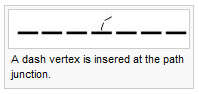
- Inserting dash vertices
- Click on the Dash vertex button, and then move the mouse pointer to the desired position on a line object or on the border of an area object and click the left mouse button. A new dash vertex is inserted. However, if there is already a vertex in this position the existing vertex is converted to a dash vertex and no additional vertex is inserted.
- Change a vertex to a dash vertex
- Click on the Dash vertex button, and then move the mouse pointer to the vertex to be converted and click the left mouse button. The vertex is changed to a dash vertex.
Comparison and Examples
Remove Vertex
![]() Remove Vertex button
Remove Vertex button
This button is enabled when a line or area object is selected. When you click on this button, the button remains pressed and the mouse pointer shows the same symbol when it is moved to the drawing window.
When this mode is selected, you can remove a vertex from a line or area object. Move the mouse pointer on the desired vertex and click the left mouse button.
You can also remove vertices in Select and Edit object or Select Object and Edit Vertex mode when holding down the Ctrl key.
Change Vertex Types to
Select Change Vertex Types to in Object Menu
Choose this command to change the symbol of all objects with a symbol A to symbol B. The Change Symbol of Objects dialog box is displayed.
This command is especially useful to translate the layers of an imported file to OCAD symbols.
- Change all objects with: Enter here the symbol number or the name of the layer of the objects to be changed. If an object is selected this edit box initially contains the symbol number or the layer name of the selected object.
- To symbol no.: Enter here the new symbol number to be given to the objects. Initially this edit box contains the number of the currently selected symbol This command is enabled when 1 or more objects are selected. This command will change the specified vertex types of all the selected objects in one step.
- Normal vertex: The Change Vertex Types dialog box is opened. Check the vertex types (normal, corner, dash, virtual gap) that should be changed to normal vertex. Click OK button to execute this command.
- Corner vertex: The Change Vertex Types dialog box is opened. Check the vertex types (normal, corner, dash, virtual gap) that should be changed to corner vertex. Click OK button to execute this command.
- Dash vertex: The Change Vertex Types dialog box is opened. Check the vertex types (normal, corner, dash, virtual gap) that should be changed to dash vertex. Click OK button to execute this command.