Eine neue Karte erstellen
OCAD verfügt über viele verschiedene Sybmolsätze, um mit dem Zeichnen von Karten sofort zu beginnen.
Eine neue Karte erstellen 


Um eine neue Karte zu erstellen und damit ein neues OCAD-Projekt anzufangen...
- Wählen Sie Neu im Datei-Menü oder klicken Sie auf die
Neu-Schaltfläche der Standard-Werkzeugleiste.
- Das Neue Datei-Dialogfenster erscheint.
- Wählen Sie einen Dateityp. Je nach Dateityp sind andere vorgefertigte Symbolsätze verfügbar. Sie können nun einen vorgefertigten Symbolsatz aus der Liste in der Mitte des Dialogs auswählen. Wenn Sie einen leeren Symbolsatz öffnen wollen, wählen Sie die Leerer Symbolsatz-Option und laden Sie diesen. Klicken Sie auf die Andere Datei-Schaltfläche, wenn Sie einen Symbolsatz von einer bereits bestehenden OCAD-Datei übernehmen wollen. Die Selektionsbox listet alle OCAD-Dateien, welche im Ordner Symbol des OCAD-Verzeichnisses abgelegt sind. Wenn Sie einen eigenen Symbolsatz zur Liste hinzufügen möchten, kopieren Sie einfach die OCAD-Datei in den Symbol-Ordner (Normalerweise C:\Programme\OCAD\OCAD11\Symbol). Symboldateien sind normale OCAD-Dateien, normalerweise ohne gezeichnete Objekte. Die Kartennotizen-Box zeigt Informationen über die Spezifikationen des Symbolsatzes, sofern diese definiert sind.
 Sie können Symbole jederzeit dem Symbolsatz hinzufügen, ändern oder vom Symbolsatz entfernen.
- - Kartennnotizen können in der Symbolvorlagen-Datei selber bearbeitet werden. Wählen Sie dazu den Karteninformationen-Menüpunkt im Karte-Menü, wenn Sie die Vorlagendatei geöffnet haben.
- - Bearbeiten Sie die Datei OrienteeringMapList.User.txt im Symbol-Ordner des OCAD-Verzeichnisses, wenn sie benutzerdefinierte Symbolsätze in der Orientierungslauf-Karte-Liste anzeigen wollen.
- Indem Sie die OK-Schaltfläche anklicken, kreiert OCAD eine neue Karte und kopiert den gewählten Symbolsatz hinein.
Massstab und Koordinatensystem 


Select the Set Scale and Coordinate System item from the Map menu. The Set Scale and Coordinate System dialog box appears.
Map Scale
Enter a scale and click the OK button or adjust the Coordinates settings.
![]() Do not use this dialog to change the scale after entering the initial values. To increase or decrease the size of the map subsequently, use the Change Scale function in the Map menu. Setting the current scale does not enlarge or reduce the map. It only changes a number in the map file and georeferencing will be lost.
Do not use this dialog to change the scale after entering the initial values. To increase or decrease the size of the map subsequently, use the Change Scale function in the Map menu. Setting the current scale does not enlarge or reduce the map. It only changes a number in the map file and georeferencing will be lost.
Georeference the Map
Before loading a georeferenced Background Map, work with GPS data or import Spatial Base Data, we recommend that you first georeference the map. You should contact your data supplier, national surveying office or cartographic institute to find out which coordinate system will best suit your needs.
Coordinates
- Choose wheter you want define Paper coordinates (in mm) or Real world coordinates. Click the corresponding radio button.
- In the Easting offset and Northing offset fields, enter the coordinate values for the center of your map.
- The coordinate system can be rotated by entering a value in the Angle field.
- In the Grid distance field, enter the desired distance for the Coordinate Grid lines.
![]() Enter the coordinate values for the center of your map in the horizontal and vertical offset fields. This is important since the drawing area of OCAD is limited to 4 x 4 m in the
Enter the coordinate values for the center of your map in the horizontal and vertical offset fields. This is important since the drawing area of OCAD is limited to 4 x 4 m in the Orienteering Standard edition, in the
Starter edition as well as in the
Course Setting edition and 80 x 80 m in the
Professional Edition. This option is used to ensure that imported Spatial Base Data, georeferenced Background Maps and GPS measurements do not lie outside the drawing area.
Coordinate System
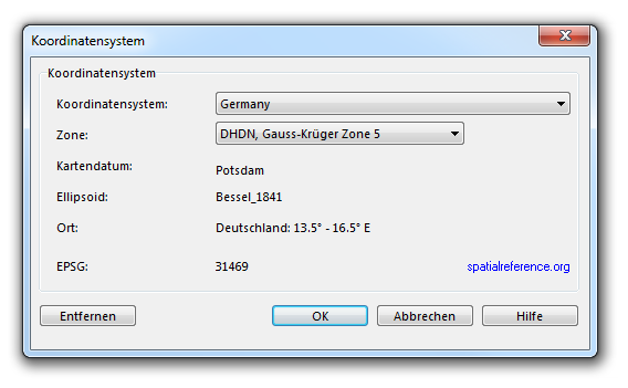
Click the Choose button to define a coordinate system. The Coordinate System dialog appears.
Choose the desired coordinate system. OCAD supports a lot of coordinate systems. The most common one is the UTM (Universal Transverse Mercator) system which is divided into 60 zones limited by meridians and defined worldwide.
- Zone: Depending on the selected coordinate system you must select a zone. If the coordinate system UTM is selected, you can click the Find button to find the correct UTM zone. This function is described in the next paragraph.
- Map datum: This field displays the map datum for the desired coordinate system (Map Datum).
- Ellipsoid: The field displays the ellipsoid from the map datum (Reference Ellipsoid).
- Location: The field displays the location, where the coordinate system can be used.
- EPSG: The field displays the EPSG-Code (European Petroleum Survey Group Geodesy) of the coordinate system.
Click the Remove button to reset the coordinate system to Grid undefined.
If you are finished, click the OK button.
Find UTM Zone
If UTM is chosen as a coordinate system, the local zone can be found with this tool. Click the Find button next to the Zone dropdown list. The Find UTM Zone dialog appears.
Enter the geographical coordinate (degree of longitude and degree of latitude) of your map.
- Latitude: Enter in this field the degrees of latitude.
- N (North): Click this button if the position is northern of the equator.
- S (South): Click this button if the position is southern of the equator.
- Longitude: Enter in this field the degrees of longitude.
- W (West): Click this button if the position is western of Prime Meridian (London Greenwich).
- E (East): Click this button if the position is eastern of Prime Meridian (London Greenwich).
Click the button OK to calculate the UTM zone. The UTM zone appears in the Coordinate system dialog box.
Example: Coordinate from Baar (Switzerland): 47° 12 North (Latitude), 8° 31' East (Longitude). Enter 47 in the Latitude and 8 in the Longitude field. You will find out that this place is in the UTM zone 32 North.
User Defined Grid
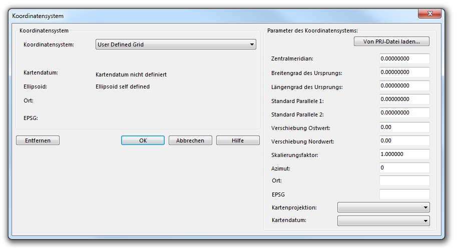
In the Coordinate System dialog you have the option to choose a User Defined Grid in the dropdown list. If you choose it, the dialog box is extended with the Coordinate system parameter part.
You can load the coordinate system from a PRJ-File by clicking the corresponding button. A PRJ-File is a projection format containing coordinate system and projection information. The coordinate system parameter are updated after loading a PRJ-File. Alternatively, the required values can be typed manually but this requires a little experience.
Additional local offset
It is possible to give an additional local offset to the chosen coordinate system. Enter a value for the horizontal and vertical offset in the corresponing fields. This is especially useful if you have to work with GPS very precisely. A tectonic plate can move but the coordinate system stays the same. If you enter a local offset, this problem can be cleared.
Click the OK button to save changes and quit the Set Scale and Coordinate System dialog.
![]() Do not use this dialog to change the real world coordinate offset if the map is georeferenced. To move a georeferenced map, use Transform -> Center Map to Drawing Area in the Map menu and enter the new offset.
Do not use this dialog to change the real world coordinate offset if the map is georeferenced. To move a georeferenced map, use Transform -> Center Map to Drawing Area in the Map menu and enter the new offset.
Previous Chapter: Graphical User Interface
Next Chapter: Colors
Back to Main Page
To the Map page.


