Ein Objekt zeichnen

Punktobjekt zeichnen 


- Wählen Sie ein Punktsymbol.
- Wählen Sie einen beliebigen Zeichnungsmodus. Der Mauszeiger wird als Fadenkreuz mit einem Punkt in der oberen rechten Ecke abgebildet.
- Klicken Sie auf die gewünschte Position im Zeichnungsfenster.
- Das Punktobjekt erscheint.
 -Um einem Punktobjekt eine bestimmte Richtung vorzugeben, drücken Sie die rechte Maustaste an der gewünschten Position und halten diese während Sie die Maus in die gewünsche Richtung ziehen. Lassen Sie die Maustaste los.
- -Die Richtung des Objektes kann auch später noch verändert werden. Selektieren Sie dafür das gewünschte Punktobjekt und wählen Sie die Schaltfläche Richtung von Flächenmustern, Punkt- und Textobjekten angeben in der Bearbeitungs- und Zeichnungs-Werkzeugleiste.
 Punktobjekte zeichnen
Linien- oder Flächenobjekt zeichnen
Sie müssen einen der acht Zeichnungsmodi wählen, um ein Linien- oder Flächenobjekt zu zeichnen. Der Mauszeiger erscheint als Fadenkreuz mit dem entsprechenden Symbol des Zeichnungsmodus in der unteren rechten Ecke.
Gerade zeichnen

- Um eine gerade Linie wie zum Beispiel für Strassen oder Hochstpannungsleitungen zu zeichnen, wählen Sie den Zeichnungsmodus Gerade.
- Wählen Sie ein Linien- oder Flächensymbol aus der Symbolbox.
- Wählen Sie den Gerade-Modus.
- Positionierten Sie den Mauszeiger an den Startpunkt der Linie, drücken Sie die linke Maustaste und halten sie, während Sie mit der Maus in die gewünschte Richtung fahren. Die Hilfelinie zeigt eine Vorschau der Linie.
- Um einen Stützpunkt hinzuzufügen, lassen Sie die Maustaste los. Drücken und halten Sie die Maustaste erneut, während Sie wieder mit der Maus in die gewünschte Richtung fahren. Wiederholen Sie diesen Vorgang nach Belieben.
- Drücken Sie die rechte Maustaste, wenn Sie mit dem Zeichnen fertig sind und die Hilfslinie wird in das entsprechende Linien- oder Flächensymbol umgewandelt.
Kurve zeichnen
Wählen Sie den Bézier-Kurven-Zeichnungsmodus, um eine fliessende oder kurvige Linien, wie zum Beispiel Höhenkurven zu zeichnen. Mit Bézier-Kurven zu zeichnen verlangt ein bisschen Übung, bis Sie ein Gefühl für Radius und Krümmung der Kurve entwickelt haben. Die Stützpunkte bestehen aus Wendepunkten mit Tangenten. Sobald Sie diese Technik beherrschen, können Sie mit dem Kurven-Zeichnungsmodus sehr effizient und genau kurvige Linien und Flächen zeichnen.

- Wählen Sie ein Linien- oder Flächensymbol aus der Symbolbox.
- Wählen Sie den Kurven-Modus
- Positionieren Sie den Mauszeiger an den Startpunkt der Kurve. Drücken und halten Sie die linke Maustaste und ziehen Sie mit dem Mauszeiger einen gewünschten Radius. Lassen Sie die Maustaste los.
- Positionieren Sie den Mauszeiger an den nächsten Wendepunkt. Drücken und halten Sie die linke Maustaste und ziehen Sie mit dem Mauszeiger den nächsten Radius. Lassen sie die Maustaste los. Die Hilfslinie zeigt eine Vorschau der Linie. Wiederholen Sie diesen Prozess nach Belieben für jeden Wendepunkt.
- Wenn Sie mit der Linie fertig sind, drücken Sie die linke Maustaste und die Hilfslinie wird in das gewünschte Linien- oder Flächensymbol verwandelt.

- -Wenn Sie mit Ihrer Tangente unzufrieden sind, drücken Sie Backspace
 . Die letzte Tangente wird gelöscht und Sie können eine neue setzen. Sie können bis zum Anfang der Linie beliebig viele Tangenten löschen. Wenn das Objekt bereits fertiggestellt wurde, ist dies nicht mehr möglich.
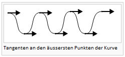
- -Sinuslinien können durch das Platzieren von Tangenten an den äussersten Punkten einfach gezeichnet werden.

- Sie können einen Eckpunkt erstellen, indem Sie zwei Tangenten den gleichen Stützpunkt geben. Kurve: Tangenten 2 und 3 starten am gleichen Punkt, führen jedoch in andere Richtungen. Ein Eckpunkt wird erstellt.

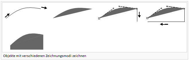
- Kurvenobjekte zeichnen

- Sie können Teile eines Linien- oder Flächenobjektes mit verschiedenen Zeichnungsmodi zeichnen. Zeichnen Sie den ersten Teil des Objektes im gewünschten Zeichnungsmodus. Drücken Sie nun die Tab-Taste, um den Zeichnungsmodus zu wechseln.

- Sie können bereits vorhandene Linien- oder Flächenobjekte verlängern. Wählen Sie dafür das gewünschte Symbol und den gewünschten Zeichnungsmodus. Drücken und halten Sie Shift
 , während Sie den ersten Stützpunkt setzen. Sie können nach diesem die Shift-Taste wieder loslassen.
 - Bereits vorhandene Objekte verlängern
- Um eine horizontale oder vertikale Linie zu zeichnen, drücken und halten Sie die Alt-Taste. Shift- und Alt-Funktionen können kombiniert werden.
Freihandlinie zeichnen
Der Freihand-Zeichnungsmodus zeichnet Bewegungen mit dem Mauszeiger auf und wandelt sie in eine Linie um. Freehand drawing mode plots the movement of the cursor and converts it into a line. Eine Linie oder eine Kurve in diesem Modus zu zeichnen ist nicht sehr effizient oder präzise. Je nach Zeichnungsgeschhwindigkeit und gewähltem Glättungsfaktor (1, 2 oder 3) wird die Linie eher eckiger, weil mehrere Stützpunkte zu einer geraden Linie verbunden werden.
- Wählen Sie ein Linien- oder Flächensymbol aus der Symbolbox.
- Wählen Sie den Freihand-Modus.
- Positionieren Sie den Mauszeiger am Anfang der Linie, drücken Sie die linke Maustaste kurz und machen Sie die gewünschten Bewegungen mit der Maus.
- Drücken Sie die linke Maustaste, wenn Sie fertig sind und die Hilfslinie wird in das gewünschte Linien- oder Flächensymbol verwandelt.
Beim Zeichnen im Freihandmodus werden gleich wie im Geraden-Modus Normalpunkte an den Ecken eingefügt. Normalpunkte beeinflussen im Gegensatz zu Eckpunkten nicht die Strichelungen von gestrichelten Linien.
Rechtwinklige Fläche zeichnen
Wählen Sie den Rechteck-Modus, um rechteckige Flächen wie zum Beispiel Gebäude oder Plätze zu zeichnen. Dieser Zeichnungsmodus erstellt in jeder Ecke einen rechten Winkel und versichert, dass Start- und Endpunkt der Fläche immer im gleichen Punkt sind.
- Wählen Sie ein Linien- oder Flächensymbol aus der Symbolbox.
- Wählen Sie den Rechteck-Modus.
- Platzieren Sie den Mauszeiger an eine der Ecken der längsten Seite der rechwinkligen Fläche. Drücken und halten Sie die linke Maustaste und ziehen Sie den Mauszeiger der längsten Seite entlang zur nächsten Ecke.
- Lassen Sie bei der nächsten Ecke die Maustaste los. Drücken und halten Sie erneut die linke Maustaste und ziehen den Mauszeiger zur nächsten Ecke. Die Hilfslinie zeigt Ihnen eine Vorschau des bereits gezeichneten. Eine gestrichelte Linie zeigt Ihnen an, wie das rechtwinklige Objekt im aktuellen Zeichnungszustand aussieht. Erschliessen Sie weitere Ecken, indem Sie den Vorgang wiederholen.
- Drücken Sie die linke Maustaste, um den Vorgang abzuschliessen. Die Hilfs- und gestrichelte Linie werden in das selektierte Flächen- oder Liniensymbol umgewandelt.
Sie sollten immer mit der längsten Seite der rechteckigen Fläche beginnen, um eine möglichst präzise Ausrichtung zu erlangen.

Rechtwinklige Linie zeichnen
Wählen Sie Rechtwinklige Linie, um rechtwinklige Linienobjekte wie zum Beispiel Gehsteige oder Treppen zu zeichnen. Dieser Zeichnungsmodus erstellt in jeder Ecke einen rechten Winkel. Der einzige Unterschied zum Rechteck-Modus ist, dass Start- und Endpunkt nicht die gleichen sind.
- Wählen Sie ein Liniensymbol aus der Symbolbox.
- Wählen Sie den Rechteckige Linie Zeichnungsmodus.
- Platzieren Sie den Mauszeiger am Anfang der rechteckigen Linie. Drücken und halten Sie die linke Maustaste und ziehen Sie den Mauszeiger entlang der längsten Seite der Linie zur nächsten Ecke.
- Lassen Sie die linke Maustaste los. Drücken und halten Sie die linke Maustaste erneut und ziehen Sie den Mauszeiger in die nächste Ecke. Die Hilfslinie zeigt Ihnen eine Vorschau der gezeichneten Linie. Erschliessen Sie weitere Ecken, indem Sie den Vorgang wiederholen.
- Drücken Sie die linke Maustaste, um den Vorgang abzuschliessen. Die Hilfslinie wird in das entsprechende Liniensymbol umgewandelt.
Sie sollten immer mit der längsten Seite der rechtwinkligen Linie beginnen, um eine möglichst präzise Ausrichtung zu erlangen.
Treppen zeichnen
Wählen Sie den Treppenmodus, um eine rechteckige Treppe zu zeichnen.
- Wählen Sie ein Liniensymbol aus der Symbolbox.
- Wählen Sie den Treppenmodus.
- Platzieren Sie die Maus am Anfang der Treppe. Drücken und halten Sie die linke Maustaste und ziehen Sie den Mauszeiger der längsten Seite der Treppe entlang zur nächsten Treppe.
- Lassen Sie die Maustaste los. Drücken und halten Sie die linke Maustaste erneut und ziehen Sie den Zeiger zur nächsten Ecke. Die Hilfslinie zeigt Ihnen eine Vorschau der gezeichneten Linie.
- Lassen Sie die Maustaste los. Drücken und halten Sie die linke Maustaste ein letztes Mal und ziehen Sie den Mauszeiger zum ersten Tritt der Treppe. Die Hilfslinien zeigen Ihnen eine Vorschau der Treppe. Lassen Sie die Maustatse los und die Hilfslinie wird in das entsprechende Liniensymbol umgewandelt.

Kreis zeichnen
Wählen Sie den Kreis-Modus, um kreisförmige Objekte wie zum Beispiel Kreisel oder Silos zu zeichnen.
- Wählen Sie ein Linien- oder Flächensymbol aus der Symbolbox.
- Wählen Sie den Kreis-Modus.
- Platzieren Sie den Mauszeiger am Rand des Objektes. Drücken und halten Sie die linke Maustaste und ziehen Sie den Mauszeiger zur gegenüberliegenden Seite des kreisförmigen Objektes. Lassen Sie die Maustaste los. Die Hilfslinie wird in das entsprechende Linien- oder Flächensymbol umgewandelt.
- -Der Kreis wird als Bézier-Kurve gezeichnet.
- -Sie können den Kreis auch vom Mittelpunkt aus zeichnen. Drücken und halten Sie dazu die Shift-Taste und ziehen Sie den Radius.
- -Das Klicken an einen Standort ohne einen Kreis zu ziehen öffnet den Kreis erstellen Dialog. Geben Sie hier den Radius in Papier- oder Landeskoordinaten ein und ein Kreis mit gewünschtem Radius wird um den geklickten Mittelpunkt erstellt.ww.ocad.com/howtos/22.htm Kreisförmige Objekte zeichnen]
- -Sie können den Kreis auch vom Mittelpunkt aus zeichnen. Drücken und halten Sie dazu die Shift-Taste
Ellipse zeichnen
Wählen Sie den Ellipse-Modus, um ovale Objekte, wie zum Beispiel Hügel oder Senken zu zeichnen.
- Wählen Sie ein Linien- oder Flächensymbol aus der Symbolbox.
- Wählen Sie den Ellipse-Modus.
- Platzieren Sie den Mauszeiger am Anfang der längeren Ellipsenachse. Drücken und halten Sie die linke Maustaste und ziehen Sie den Mauszeiger zum anderen Ende der Ellipsenachse.
- Lassen Sie die Maustaste los. Platzieren Sie den Mauszeiger an den Anfang der kürzeren Ellipsenachse. Drücken und halten Sie die linke Maustaste und bewegen Sie die Achse an die gewünschte Position. Lassen Sie die Maustaste los und die Hilfslinie wird in das entsprechende Linien- oder Flächensymbol umgewandelt.

- Die Ellipse wird als Bézier-Kurve gezeichnet.
- Elliptische Objekte Zeichnen
Mehrere Punktobjekte zeichnen
Dieser Zeichnungsmodus eignet sich, um mehrere Punktsymbole mit gleichem Abstand auf einer Linie zu zeichnen.
- Wählen Sie ein Punktsymbol aus der Symbolbox.
- Wählen Sie den Mehrere Punktobjekte zeichnen Zeichnungsmodus.
- Zeichnen Sie eine Linie von der Position des ersten bis zur Position des letzten Punktobjektes.
- Der Dialog Mehrere Punktobjekte zeichnen erscheint:

Geben Sie die Anzahl gewünschter Punktobjekte ein und drücken Sie OK.
Die gewünschte Anzahl Objekte werden gezeichnet:
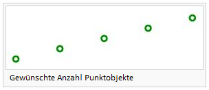
- Beträgt die Anzahl Objekte 1, wird das Objekt in der Mitte der Linie gezeichnet.

Laser-Distanzmessgerät Zeichnungswerkzeug
Laser-Distanzmessgerät Zeichnungswerkzeug.
Nummerischer Modus
Wählen Sie den Nummerischen Modus, um Messdaten oder Koordinaten für bestimmte Objekte einzugeben.
Erstellen Sie Punktobjekte mit Hilfe von Distanz- oder Azimutmessungen.
- Wählen Sie ein Punktsymbol aus der Symbolbox.
- Wählen Sie Nummerischer Modus.
- Geben Sie die Koordinaten Ihres Standortes in die Felder Ostwert und Nordwert ein. Ein kleines Kreuz markiert die Position im Zeichnungsfenster.
- Geben Sie die Länge (in mm oder m) im Länge-Feld und den Winkel im Uhrzeiger- oder Gegenuhrzeigersinn ein.
- Drücken Sie Beenden.
- Die Winkel- und Distanzmessungen werden verwendet, um das Punktobjekt richtig zu platzieren.
- -Sie können den Winkel zwischen Uhrzeiger- und Gegenurzeigersinn wechseln, indem Sie auf die entsprechenden Schaltflächen klicken.
- -Sie können die Distanzeinheit zwischen Meter und Millimeter wechseln, indem Sie auf die entsprechenden Schaltflächen klicken.
Construct a line or area object using coordinate pairs.
- Select a line or area symbol from the symbol box.
- Select Numeric mode.
- Enter the coordinates of your first coordinate pair in the Easting and Northing fields. A small gray cross highlights the position of the first coordinate pair in the drawing window.
- Select the construction mode
 Enter positions.
 - Enter the coordinates of the second coordinate pair in mm or m and click Next. A help line appears between the first and second coordinate pair. Repeat this process as often as necessary; the help line is extended each time. Click End once you have entered the final coordinate pair.
- The sections are then transformed into the selected line or area symbol.
Construct a line or area object using distance or azimuth measurements.
- Select a line or area symbol from the symbol box.
- Select Numeric mode.
- Enter the coordinates of your starting point in the Easting and Northing fields. A small cross highlights the position of the starting point in the drawing window
- Select the construction mode
 Enter length and angle.
 - Enter the length in mm or m in the Length field and enter the Angle in a clockwise or counterclockwise direction. A help line appears that displays the distance and azimuth from the starting point. Repeat this process as often as necessary; the help line is extended each time. Click End once you have entered the final distance and azimuth values.
- The sections are then transformed into the selected line or area symbol.
Textobjekt platzieren
Text and line text symbols are available for placing text. Text symbols are generally aligned horizontally. Line text symbols follow the flow of rivers or streets.
Place a text object
You can choose text frames or anchor points for placing text objects.
Define a text frame
- Select a text symbol from the symbol box.
- Select a drawing mode.
- Position the cursor on the upper left-hand corner of the desired text frame, then click and hold the left mouse button and drag the cursor to the lower right-hand corner. Release the mouse button. The text cursor for inputting text appears.
- Enter the desired text. The line break is added automatically Press Enter to start a new paragraph.

Define a text anchor point
- Select a text symbol from the symbol box.
- Select a drawing mode.
- Position the cursor at the point where the text is to be anchored. Release the mouse button. The text cursor for inputting text appears.
- Enter the desired text. Press Enter to start a new paragraph.
Place a Line Text Object
Select a Line Text symbol if you want your text to follow the flow of a curve.
- Select a Line Text symbol from the symbol box.
- Select Bézier Curve mode.
Draw a curve
- Once you have finished drawing the line, a help line appears as well as the text cursor for inputting text.
- Enter the desired text.

Edit a vertex:
To edit a vertex, select the Select Object and Edit Vertex editing mode. You will then be able to move, delete or change the type of vertex.
For point objects, the middle of the symbol is represented by a large square ![]() . For line and area objects, the first point of the object is represented by a large square
. For line and area objects, the first point of the object is represented by a large square ![]() , vertices by small squares
, vertices by small squares ![]() , and the last point of the object by a cross X. With Bézier curves, circle symbols
, and the last point of the object by a cross X. With Bézier curves, circle symbols ![]() are used to represent the ends of the tangents.
are used to represent the ends of the tangents.

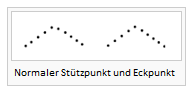
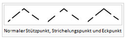
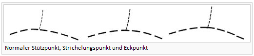
When drawing broken or dotted lines in OCAD, the dashes and spaces always have the same length. You will never get half dashes or spaces; the dashes are distributed proportionally across the entire object. However, if you add a corner vertex, the dashes before and after the vertex are calculated separately. A corner vertex is made up of two adjoining dashes; a dash point is positioned at the center of a single dash (the dash is therefore split in the middle). Corner vertices and dash points are therefore used to define the appearance of corners and intersections.
The following functions are available for editing vertices and influencing dashed lines:
 Remove Vertex: Remove a vertex from the object. Alternatively, you can press the Ctrl button and then click the vertex.
- Different point types
- Every vertex can be changed into a different kind of vertex. To do this, simply select the vertex type you want and then click the vertex object to change it.
- Influencing dashed lines


Tastatur zusammen mit der Maus einsetzen
Zeichnen
- Continue an existing line: Press the Shift key and click the end point of the line to be continued. This can be used instead of the
 Verschmelzen function.
 - Draw horizontal or vertical lines: Press the Alt key while drawing. The line snaps in a vertical or horizontal direction. This can be useful when drawing a border or north lines. This function is also available in the OCAD 11 CS Edition.
- Existierenden Objekten folgen: Hold the Ctrl key and click with the Left Mouse Button a point on the line to be followed. The Ctrl key can be released now. Keep the Left Mouse Button pressed and release it at the point the following shall stop. The drawing of the line can be continued now.
- Change drawing mode during drawing and editing: Press the Tab key until the desired drawing mode appears to change the drawing mode.
Bearbeiten
- Delete Stützpunkte from line or area objects: Hold the Ctrl key and click the vertex with the Left Mouse Button. See also: Stützpunkt entfernen
- Add Normal Vertices to line or area objects: Hold the Shift and the Ctrl key pressed and click the corresponding point on the line with the Left Mouse Button. See also:
 Normalen Stützpunkt hinzufügen
 - Select an object under a already selected object: Hold the Alt key and click the object above the object to be selected. This function only has an effect if you are clicking near a Stützpunkt of the object above.
- Move the selected object: Use the Arrow keys to move a selected object. For more information about selecting and moving objects visit the Selektieren page.
- Select multiple objects: Hold the Shift key and click the objects to be selected one after another. As an alternative, drag an area with the Right Mouse Button in the
 Selektiere und editiere Objekt or
  Selektiere Objekt und editiere Stützpunkt mode to select all objects which are in it. Read the Selektiere und editiere mehrere Objekte article for more information.
Schneiden
- Select next object: Select a line object and choose the
 Linie schneiden function. If you press the Alt key, the cursor changes to the Selektiere Objekt und editiere Stützpunkt mode. Keep the Alt key pressed and click the next object you want to cut. Release the Alt key and continue with the cutting.
 - Insert a virtual gap: Select a line object and choose the Linie schneiden function. If you press the Ctrl key while cutting, a virtual gap is inserted. A virtual gap is graphical gap only: the line is not interrupted.
- Dashed line: Insert a gap at the cutting point: Select a dashed line object and choose the Linie schneiden function. Hold the Shift key while cutting a dashed line to insert a gap with the same length, as the other gaps in the dashed line, at the cutting point.
Existierenden Objekten folgen
Ctrl button: Following existing objects
Area objects are often limited by line objects. You can trace existing line or area objects without having to redraw them.
- Select a line or area symbol from the symbol box.
- Select a drawing mode.
- Press and hold the Ctrl button, then position the cursor at the point from which you want to trace the line. This does not have to be the start or end point of the line. The help line will appear with its vertices.
- Click and hold the left mouse button and drag the cursor to the desired point. This does not have to be the start or end point of the line.
- Release the mouse button. The traced line is transformed into the selected line or area symbol.

- -With double lines (e.g. streets), you can trace the middle line as well as both side lines. If you do not require this option, you can deactivate it under Preferences, Drawing in the Options menu.
- -Line tracing is only possible in straight, Bézier and freehand mode.
- -It is possible to trace the outline of existing area objects. However, it is only possible to trace up to one half of the outline, otherwise the trace would be in the opposite direction. The point, up to which the object can be traced, is represented by a large (the same symbol used for the first point of an object).
- Following existing objects
Objekt editieren
To edit an object, you must select the Select and Edit object mode. As soon as you have selected the object, the object frame appears with anchor points ![]() . You can now move, rotate, cut, stretch or reduce the size of the object or use the following functions:
. You can now move, rotate, cut, stretch or reduce the size of the object or use the following functions:

 Duplicate object: Duplicate the selected object. Alternatively, press Ctrl + C und Ctrl + V.
 Indicate direction of area pattern, point or text object: Change the direction of the selected point or text object or the structure of the selected area object.
 Rotate Object: Rotate the selected object around a defined rotation point.
 Move parallel: Move the selected line object in a parallel direction or stretch or reduce the size of the selected area object.
- Move parallel with distance
- -Only for line, area and line text objects
- -Positive values move the object to the right side, negative to the left.
- -'Move': Move the selected object
- -'Duplicate': Make a copy and move the copy to the new position
 Fill or make border: Fill in a hole in the selected area object using an area symbol or draw a border around the hole using a line symbol. Fill in the selected line object using an area symbol or combine the selected area object with an area symbol.
Holes in areas often need filling. With OCAD you can draw a border around a hole using a line symbol or fill in a hole using an area symbol.
- Select a hole by clicking it.
- Select a line or area symbol from the symbol box.
- Select Fill or make border. A border is drawn around the hole using the selected line object or it is filled in using the area object.
- After selecting a line or area object, you can combine it with another symbol. Select the object, then choose the desired line or area symbol from the symbol box and click Fill or make border. The duplicated object will be positioned above or below the selected object.
 Find selected objects: Display the selected objects in the center of the drawing window.
 Change symbol of object: Assign a new symbol to the selected object.
 Change symbol of all objects with this symbol: Assign a new symbol to all objects with a specific symbol.
 Join: Join the ends of selected line objects that have the same symbol.
- Join and merge objects
 To Curve: Change the selected freehand line into a Bézier curve. Select smooth level in toolbar.
 To Graphics: Break down the selected object into its graphical elements or display the outlines of the respective elements.
Change from drawing mode to one of the editing modes (Select and Edit object or Select Object and Edit Vertex) to edit an object. Click the Select and Edit object or Select Object and Edit Vertex button to do this. The cursor appears as either a solid or transparent arrow.
- A context menu appears when you press the right mouse button and you can change from drawing mode to editing mode and vice-versa. By deactivating the Context menu option under OCAD Preferences, GUI in the Options menu you can switch from drawing mode to editing mode, and vice-versa, by simply clicking the right mouse button.
Snapping
Previous Chapter: Import Files
Next Chapter: Select
Back to Main Page