Beispiel Spitze Linie: Unterschied zwischen den Versionen
Zur Navigation springen
Zur Suche springen
Admin (Diskussion | Beiträge) K (moved Example: Pointed line to Example Pointed line) |
Admin (Diskussion | Beiträge) Keine Bearbeitungszusammenfassung |
||
| Zeile 1: | Zeile 1: | ||
[[File:PointedLine.PNG]] | |||
[[File: | |||
To create this symbol, start from an empty line symbol and then do the following steps: | To create this symbol, start from an empty line symbol and then do the following steps: | ||
In the Main Line page: | In the Main Line page: | ||
# Choose the Line color. | # Choose the Line color. | ||
| Zeile 10: | Zeile 10: | ||
# Also enter the length of the point in '''Distance to the end'''. | # Also enter the length of the point in '''Distance to the end'''. | ||
# Check '''Pointed ends'''. | # Check '''Pointed ends'''. | ||
[[File:PointedLine_MainLine.PNG]] | |||
Back to: : [[Chapter 6: Create a New Symbol]] | Back to: : [[Chapter 6: Create a New Symbol]] | ||
Version vom 31. Oktober 2011, 14:14 Uhr
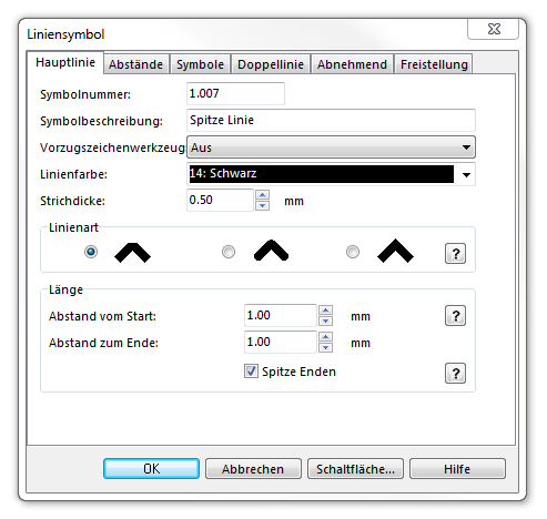
To create this symbol, start from an empty line symbol and then do the following steps:
In the Main Line page:
- Choose the Line color.
- Enter the Line width.
- Enter the length of the point (the length of the taper) in Distance from start.
- Also enter the length of the point in Distance to the end.
- Check Pointed ends.
Back to: : Chapter 6: Create a New Symbol

