Beispiel Gondelbahn: Unterschied zwischen den Versionen
Zur Navigation springen
Zur Suche springen
Admin (Diskussion | Beiträge) Keine Bearbeitungszusammenfassung |
Admin (Diskussion | Beiträge) Keine Bearbeitungszusammenfassung |
||
| Zeile 7: | Zeile 7: | ||
[[File:CableCar_MainLine.PNG]] | [[File:CableCar_MainLine.PNG]] | ||
In the Distances page: | |||
# Enter the length of the dash in Main length a. | |||
# Also enter the length of the dash in End length b. | |||
[[File:CableCar_Distances.PNG]] | |||
In Symbols page: | |||
# In the box Main symbol A click Edit to go to the symbol editor. There you draw the desired line. | |||
[File:CableCar_SymbolEditor.PNG]] | |||
In Framing page: | |||
# Enter '''Line color''' and '''Line width'''. | |||
[[File:CableCar_Framing]] | |||
Back to [[Create a New Symbol]] | |||
Version vom 31. Oktober 2011, 16:57 Uhr
To create this symbol, start from an empty line symbol and then do the following steps:
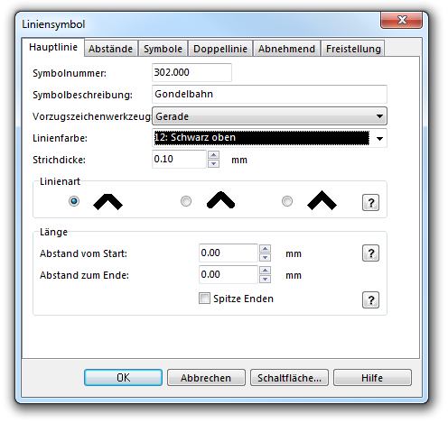
In the Main Line page:
- Enter Line color and Line width.
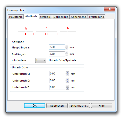
In the Distances page:
- Enter the length of the dash in Main length a.
- Also enter the length of the dash in End length b.
In Symbols page:
- In the box Main symbol A click Edit to go to the symbol editor. There you draw the desired line.
[File:CableCar_SymbolEditor.PNG]]
In Framing page:
- Enter Line color and Line width.
Back to Create a New Symbol


