Map
Optimize and Repair 


Choose this command in the Map menu to optimize (reduce) the size of the map file and repair damaged objects. With edit operations such as deleting objects, empty space is created in the map file. This function removes this empty space and therefore reduces the size of the map file.
When OCAD encounters damaged objects it tries to repair them. If this is not possible, they are deleted.
After the optimization the Optimization Result dialog box is displayed with the following information:
- File size before optimization in bytes.
- File size after optimization in bytes.
- Objects repaired
- Damaged objects deleted
- Spurious objects deleted: Spurious objects are objects which are not visible. These may be text objects with no text and no line, line objects with only one point, or area objects with only 2 points.
- Unsymbolized Objects
- Objects with Unknown Symbol
- Objects with Invalid Symbol Type
Set Scale and Coordinate System 


Visit the Set Scale and Coordinate System page to get some information about this function.
Change Scale 


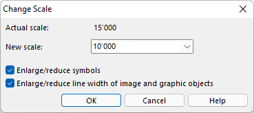
Choose this command in the Map menu to change the scale of the map. The map is enlarged/reduced according to the new scale. The Change Scale dialog box is displayed, where the new scale can be entered.
Actual scale
This line shows the current scale of the map. Choose the Set Scale and Coordinate System command from the Map menu to set the current scale.
![]() Setting the current scale with the Set Scale and Coordinate System function does not enlarge or reduce the map. It only changes a number in the map file.
Setting the current scale with the Set Scale and Coordinate System function does not enlarge or reduce the map. It only changes a number in the map file.
New scale
Enter here the desired new scale of the map. You may choose one of the predefined scales or enter the scale on the keyboard.
Enlarge/reduce symbols
Check this box to enlarge/reduce the symbols with the same factor as the map. When the box is checked, the map is enlarged/reduced like a photographic enlargement. When this box is not checked, the map is enlarged/reduced, but the symbols are kept in the same dimension.
Enlarge/reduce line width of image and graphic objects
Check this box to enlarge/reduce line width of image and graphic objects with the same factor as the map.
![]() Course Setting project: OCAD does not enlarge and reduce symbols with symbol numbers 0-100. That are usually the symbols for the control description.
Course Setting project: OCAD does not enlarge and reduce symbols with symbol numbers 0-100. That are usually the symbols for the control description.
Click the OK button to finish.
Create Map Grid 


Choose this command from the Map menu to create grid lines on the map (e.g. it can be used to draw Magnetic North lines or the grid for a Name Index.). The Create Map Grid dialog box is displayed.
Now, you have to make the following adjustments:
- Easting offset: Enter the easting offset to the defined map grid for the vertical grid lines.
- Northing offset: Enter the northing offset to the defined map grid for the horizontal grid lines.
- Create vertical grid lines: Check this option to create vertical grid lines and enter the distance .
- Create horizontal grid lines: Check this option to create horizontal grid lines and enter the distance .
- Angle: OCAD uses the real world angle.
- Create vertices at grid junctions: Check this option to create a vertex at every grid junction.
- Symbols:
- Grid lines: Select a line symbol for the grid lines (map grid).
- Grid labels: Select a text symbol for the grid labels.
Click the OK button when finished. The grid is drawn over the whole map. Therefore, remove background maps which are larger than the map before creating a grid.
![]() Create Name Index is the corresponding function to create a name index based on a rectangular map grid.
Create Name Index is the corresponding function to create a name index based on a rectangular map grid.
![]() The minimum and maximum grid line distance depends on the map grid distance. You can change this grid distance in Set Scale and Coordinate System dialog.
The minimum and maximum grid line distance depends on the map grid distance. You can change this grid distance in Set Scale and Coordinate System dialog.
Create WGS84 Grid 

Read more about this topic on the Create WGS84 Grid page.
Hide 


Choose this command in the Map menu to hide the map on the screen.
Transform
Information about the transforming functions, which are Move, Stretch/Shrink, Mirror, Rotate Map, Change Coordinate System, Affine, Rubbersheeting, Local Transformation and Center Map to Drawing Area, can be found on the Map Transform page.
Convert Imported Layers to Symbols 


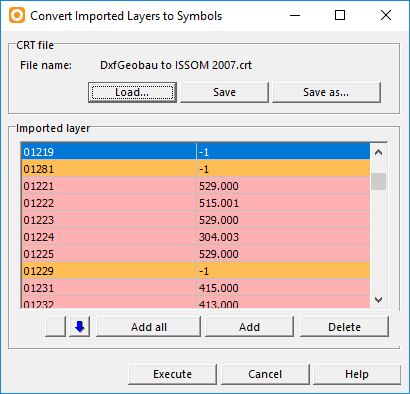
Choose this command from the Map menu to convert the layers of an imported DXF, Shape or AI file to symbolized objects. The Convert Imported Layers to Symbols dialog box appears.
In this dialog box you can create a list of references. A reference consists of a layer and the corresponding OCAD symbol. You can save the list to a cross reference (.ocdCrt) file for later use. You can load an existing cross reference file to modify or execute it.
Visit the Cross Reference Table page to get some information about CRT-Files and the CRT-File part in the dialog.
Click the Execute button when you are finished with editing the CRT-File. The conversion gets executed.
Click Add all to add all imported layers to the table.
![]() - Please note that this CRT file does not work to Import OCD Files!
- Please note that this CRT file does not work to Import OCD Files!
- An imported layer can be converted manually. Visit the Convert a Layer Manually page to get more information.
Convert Area or Line Objects to Point Objects 

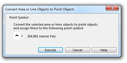
Choose this function in the Map menu to convert area or line objects to point objects. This command is enabled if an area or line object is selected.
- Select a line or an area object.
- The Convert Area or Line Objects to Point Objects dialog appears.
- Choose a point symbol. You may have to create a Symbol first that looks like the old one. Read here how to create a Point Symbol out of vector data.
- Click the Execute button. The selected area or line object is converted to a point symbol and the chosen symbol is assigned to it.
- You may need to shift the point symbol until it is at the right place.
![]() The point symbol appears in the middle of the area or the line.
The point symbol appears in the middle of the area or the line.
Examples
- Import PDF and convert to symbol
A typical example for this function would be the import of a PDF. Vector objects in PDF-Files are imported as Image Objects and can be converted to symbols.
In the image below, you see a symbol for a post office and a car park. However, each of these symbols consists of one or several area objects. Because of that, editing and moving around these symbols can get tedious. That's why it is an option to create a new Point Symbol out of the Vector Data and later convert the area objects to this new Point Symbol.
- Convert a Line or Area Object to a Point Object
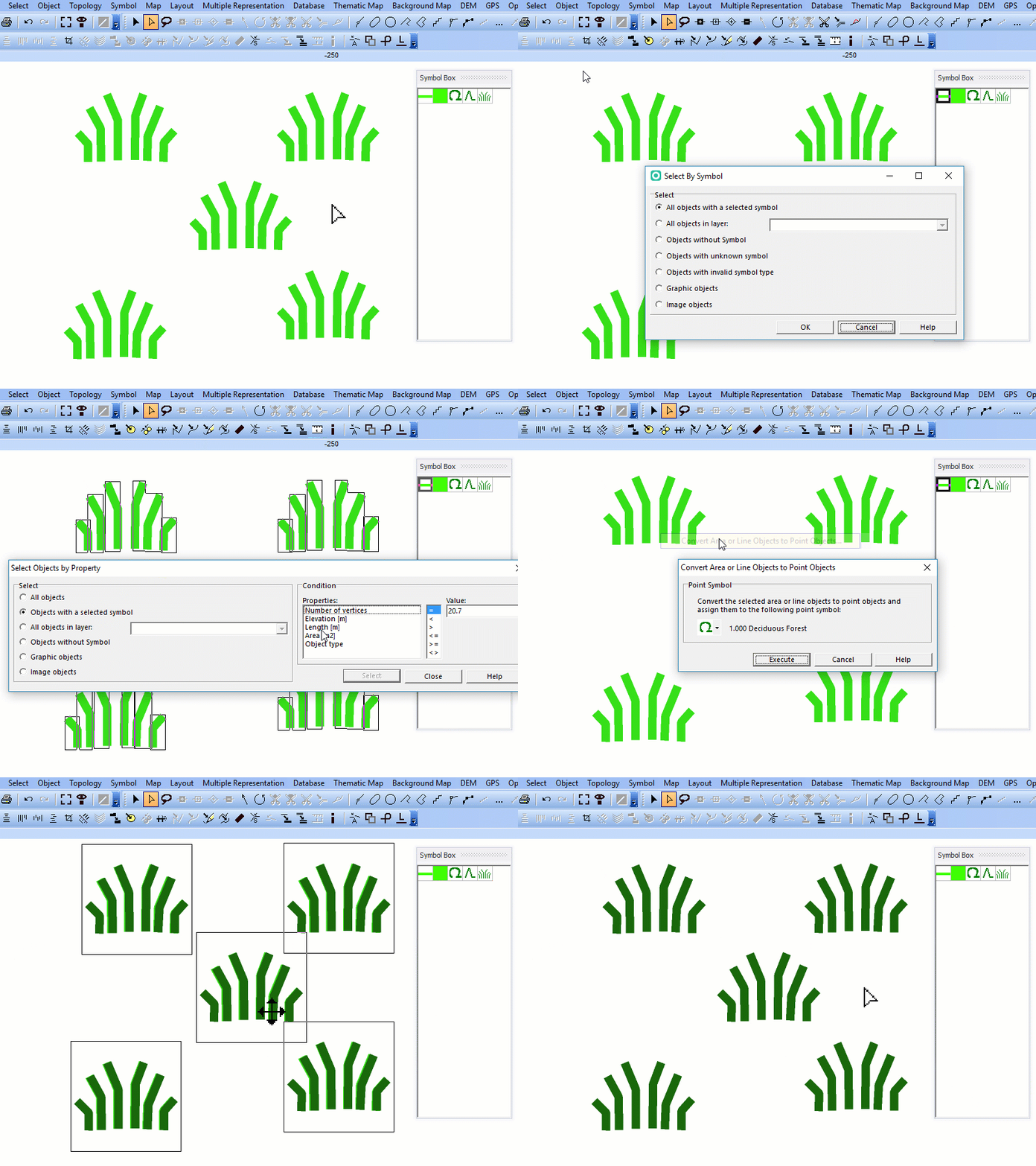
In the next example the map contains a symbol for coniferous and deciduous forest and a symbol for heather. The animation shows how to convert them to point symbols.
- Convert multiple Line Objects to a Point Object
Here's the problem: We have a symbol consisting of 6 line objects, in our example the symbol for 'Heather, which appears 5 times. Now, if we select all six objects of these 5 symbols, we will get 30 Point Symbols, but only want to have 5. That's why we try to find an unique property of the objects we want to convert to identify only one specific object per symbol.
So, we first select all 30 objects and select them by property in a next step.
Now we only have one selected object for every symbol, which we can convert to a Point Object.
Shift the Symbols until they are at the right place.
Convert Text Objects to Point Objects 

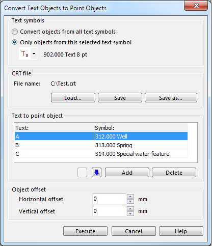
Choose this command from the Map menu to convert text to point objects. The Convert Text Objects to Point Objects dialog appears.
This function is used after import map drawn in DTP program. In a DTP program point symbols are often drawn with a character and a special symbol fonts. OCAD can convert this characters to a point symbol.
In the first part of the dialog you can decide wheter you want to convert the objects from all text symbols or only objects from a selected symbol.
In the second part of the dialog box you can create a list of references. A reference consists of a layer and the corresponding OCAD symbol. You can save the list to a cross reference (.ocdCrt) file for later use. You can load an existing cross reference file to modify or execute it.
Visit the Cross Reference Table page to get some information about CRT-Files and the CRT-File part in the dialog.
Example of crt file:
 312.000 A
 313.000 B
 314.000 C
The same data in the dialog:
Click the Execute button when you are finished with editing the CRT-File. The conversion gets executed.
Convert Text Objects from OEM to Unicode 

Choose this command from the Map menu to convert text objects from OEM to Unicode.
This function can be used after importing geodata from non-Unicode compatible programs or open ocd files from older OCAD versions. OCAD is Unicode compatible.
In the first part of the dialog you can decide wheter you want to convert the text from all text symbols or only objects from a selected symbol.
In the second part of the dialog box you can create a list of references. A reference consists of a layer and the corresponding OCAD symbol. You can save the list to a cross reference (.ocdCrt) file for later use. You can load an existing cross reference file to modify or execute it.
Visit the Cross Reference Table page to get some information about CRT-Files and the CRT-File part in the dialog.
Click the Execute button when you are finished with editing the CRT-File. The conversion gets executed.
Example: After opening OCAD 7 file in OCAD 2018 some characters are invisible (e.g. the character Ť from codepage Windows-1250 to represent texts in Central European and Eastern European languages). Use this function to convert this character from OEM code '141' to the Unicode '356'.
Export Objects by Selected Symbols 


With this function you can export objects with the selected symbol(s) in a new OCAD-Map. Select the desired symbol(s) before choosing this function (e.g. you can export all roads).
Choose this function from the Map menu. The Export Objects by Selected Symbols dialog opens. Browse a location and enter a name for the new file. Then, click the Save button to finish.
Export Selected Objects 


With this function you can export the selected object(s) in a new OCAD-Map. Select the desired object(s) before choosing this function.
Choose this function from the Map menu. The Export Selected Objects dialog opens. Browse a location and enter a name for the new file. Then, click the Save button to finish.
Delete Objects by Selected Symbols 

Choose Delete Objects by Selected Symbols in the Map menu to select all objects with certain symbols or in a certain layer. As an example you can select all roads. The Delete Objects by Selected Symbols dialog box appears.
All objects with a selected symbol
Choose this option and click on the OK button to delete all objects with the selected symbol(s). Select the symbol(s) before you choose the Delete Objects by Selected Symbols command.
All objects in layer
If you import files like PDF, DXF, Adobe Illustrator or OpenStreetMap with layer information, the layer information does not get lost, though OCAD does not support layers as they are known in Adobe Illustrator or similar applications. Choose the All objects in a layer option to delete all objects which are in the same layer. Choose a layer in the dropdown list.
Unsymbolized objects
Choose this option and click on the OK button to delete all Unsymbolized Objects.
Objects with unknown symbol
Choose this option and click on the OK button to delete all Objects with Unknown Symbol.
Objects with invalid symbol type
Choose this option and click on the OK button to delete all Objects with Invalid Symbol Type.
Graphic objects
Choose this option and click on the OK button to delete all Graphic Objects.
Image objects
Choose this option and click on the OK button to delete all Image Objects.
Export Part of Map 


With this function you can export a part of the current map in a new OCAD-Map.
Choose this function from the Map menu. The Export Part of Map dialog opens on the right side of the screen. The following adjustments can be made:
Boundaries
- Rectangular boundaries: Choose this option to export a rectangular part of the map. You can modify or move the boundaries using the mouse.
- Click
Setup button to define the region to be exported with coordinates. The Setup Part of Map (Export) dialog box appears.
- Click the
Entire Map button to export the entire map. The boundary rectangle adjusts to the entire map.
- Click the
To Current View button to export the map which is currently displayed on the screen. The boundary rectangle adjusts to the current view.
- Use selected object for boundaries: Choose this option to export an irregularly shaped part of the map. Before choosing the Export Part of Map command, you must draw the shape with a line or area object.
- Export with selected object: If you check this option the object which defines the boundary is exported as well.
 To make this function faster convert this cutting object from a curve to a polyline (Change to Polyline).
 The number of vertices of the cutting object has a big influence on the speed of this function.
 This option may produces inverted area objects or other artefats. Namely if the cutting object has self-intersections or if the cutting object crosses a hole of an area object.
 We recommend to use the Rectangular boundaries option to export a rectangular part of the map.
- Export database links: This option is checked by default. If you do not want to export the database links, then uncheck this option. This will speed up the export significantally if the map has a lot of linked objects.
Click the OK button when finished. The Export Part of Map dialog opens. Browse a location and enter a name for the new file. Then, click the Save button to finish.
Colors 


You can find all information about colors on the Colors page.
Define Spot Colors 


Visit the Define Spot Colors page to get some information about this function.
Load Colors From 


Information about this function can be found on the Colors page.
Load Colors and Symbols From 


Information about this function can be found on the Colors page.
Compare Symbols and Colors 


Select this command in the Map menu to compare the symbol set of the open file with a reference OCAD map. The Reference map dialog appears. Choose a reference file and click the Open button. The Compare Symbols and Colors dialog box appears. You have the following options:
- Compare colors: Activate this check box if the color table shall be compared.
- Compare symbols: Activate this check box if the symbols shall be compared.
- Used symbols only: Activate this checkbox if only used symbols shall be compared.
- List identical symbols: Activate this check box if the identical symbols shall be listed, too. If this check box is deactivated, only the different symbols will be logged in the TXT-File.
Click the OK button to continue. OCAD saves a text file to the location of the currently opened OCAD-Map under the name FILENAME.CompareResult.txt and opens it. Make sure that the directory of the current OCAD-Map is not a read-only folder.
The Logfile shows the difference of the symbols and/or colors and if wanted also the identical symbols.
Load Symbol Descriptions From
Choose this command in the Map menu to load symbol descriptions from a text file. Choose the Load Symbol Descriptions From... item from the Map menu. The Load dialog box is displayed. Choose a text file what contains the symbol descriptions. Click the Open button to load the symbol descriptions.
The text file needs to contain the symbol number followed by a SPACE or TAB as separator and the symbol description, ex:
- 101.000 Contour
- 102.000 Index Contour
Save Symbol Descriptions To
Choose this command in the Map menu to save the symbol descriptions to a text file. Select the Save Symbol Descriptions From... item from the Map menu. The Save dialog box is displayed. Choose a path and file name. Click the Save button to save the symbol descriptions. The text file contains the symbol number followed by a TAB as separator and the symbol description, ex:
- 101.000 Contour
- 102.000 Index Contour
Symbol Set Report 


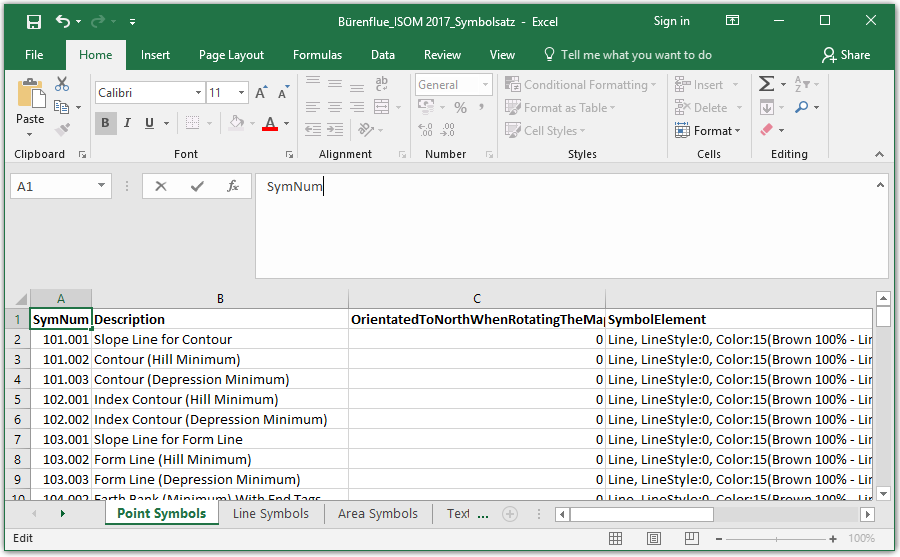
Choose this command to save an Excel-file with a detailed description of all symbols in your file.
Symbol Set Conversion 


Visit the Symbol Set Conversion page to get some information about this function.
Update Symbol Set 


Use this function to update maps drawn with ISOM 2017 to the new ISOM 2017-2 standart.
Visit the Update Symbol Set page to get some information.
Renumber Symbols 

Use this function to renumber symbols and objects with a crt file.
Example of a crt file: The first value is the old symbol number, the second the new one.
 101 10101
 102 10102
The new symbol number can't be any old symbol number, even if you change this number later on.
101 102
102 101
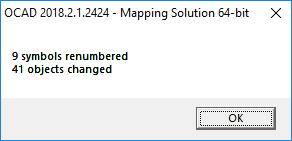
The result is shown in a info message.
Use the function Save Symbol Descriptions To to get all symbol numbers as a text file.
Check Legibility 


Use this function to check minimum distances between objects, minimum length of line objects or minimum size of area objects according to ISOM 2017. This function will help map makers to find the right degree of generalisation. Furthremore, Event Advisers and Map Consultants have a tool to check the maps.
![]() --> See a short video on YouTube, which explains you the basics.
--> See a short video on YouTube, which explains you the basics.
![]() There are also tools in OCAD that check the legibility of orienteering maps directly during drawing.
There are also tools in OCAD that check the legibility of orienteering maps directly during drawing.
- Ckeck for objects: Choose if you want to check all objects or only the objects with a selected symbol (they need to be selected before).
- Extend: Check Entire map or only Current View. Current view is the part of the map which is shown on the screen.
- Check distance between objects: Default value is 0.15 mm for map scale 1:15'000. The default value is adapted automatically for larger scales like 1:10’000 (0.23 mm).
- Check distance only between object from the same color group (black, brown, blue, green, yellow): It is recommended to check this option for orienteering maps, as many objects of differnt colors overlap (e.g. brown contour line through green vegetation).
- Check distance between contours: Minimum distance between contours are checked. 'Invisible' conflicts (e.g. contour distance conflicts below cliffs) will be ignored.
- Check minimum line length: Minimum length values from ISOM 2017 are checked.
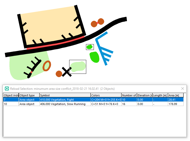
- Check minimum area size: Minimum area size and width values from ISOM 2017 are checked.
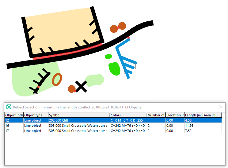
Click the OK button. Three different selections will be stored (minimum distance conflict, minimum line length conflict, minimum area size conflict). Reload the selections under Reload Selection in the Select menu. The latest selections are at the bottom of the list.
Once you have opened a selection, go through the conflics by clicking on the corresponding objects in the table.
Minimum distance conflics will not only be stored in a selection, but also shown with red dots or lines. Therefore, two new symbols will be added at the bottom of your symbol box.
![]() If you want to delete these red conflict dots and lines, select them by using Reload Selection in the Select menu or by right-clicking the symbol(s) in the symbol box and Select objects by symbol....
If you want to delete these red conflict dots and lines, select them by using Reload Selection in the Select menu or by right-clicking the symbol(s) in the symbol box and Select objects by symbol....
If you uncheck the option Check distance only between object from the same color group (black, brown, blue, green, yellow), you will get more conflicts and the result will look like this.
Selection for minimum line length.
For the option minimum area size, OCAD compares the area size of an object with its minimum dimension according ISOM 2017. However, please be aware that most symbols do not only have minimum area sizes, but also a minimum width. OCAD does not check the minimum width.
Minimum area size dimension according ISOM 2017-2.
Show Impassable Features 


Visit the Show Impassable Features page to get some information about this function.
Routing 

Visit the Routing page to get some information about this function.
Map Information 


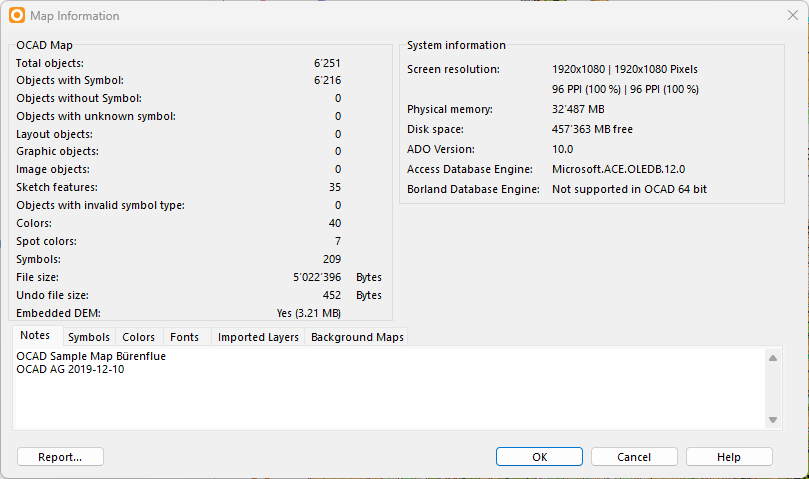
Choose this command from the Map menu to get some information about the current map and about the Windows system. The Map Information dialog box is displayed.
The dialog box provides the following information:
- Total objects: The total number of objects on the map.
- Objects with symbol: The total number of symbolized objects on the map.
- Objects without symbol: The total number of Unsymbolized Objects on the map.
- Objects with unknown symbol: The total number of Objects with Unknown Symbol on the map.
- Layout objects: The total number of Layout Objects on the map.
- Graphic objects: The total number of Graphic Objects on the map.
- Image objects: The total number of Image Objects on the map.
- Sketch objects: The total number of Sketch Objects on the map.
- Objects with invalid symbol type: The total number of Objects with Invalid Symbol Type on the map.
- Colors: The total number of Colors.
- Spot Colors: The total number of Spot Colors.
- Symbols: The total number of Symbols.
- File size: The size of the map file on the disk in Bytes.
- Undo file size: The size of the undo file in the temporary OCAD folder in Bytes. The undo file is used for Undo/Redo.
- Ebmedded DEM: Shows if there is an Ebbedded DEM and how large it is.
In addition, you can choose between several tabs with detailed information:
- Notes: Enter information about the map here. This feature was called File information until OCAD 9. The text you type in here will show up in the New File dialog under Map notes if you use the map as a symbol template.
- Symbols: This tab shows a tree view of all Symbols in the Symbol Box.
- Colors: This tab shows a tree view of all Colors in the color table and in which symbols they are used.
- Fonts: This tab shows a tree view of all used fonts and in which symbols they are used.
- Imported Layers: This tab shows all layers that have been imported to the map file.
- Background Maps: This tab shows a tree view of all Background Maps loaded.
- Database: This tab shows a tree view of all connected Databases in the map. Only in Mapping Solution Edition.
Click the Report button to save a report of the selected tab as a XLS or TXT File.
The right part of the dialog is the System information part with the following information:
- Screen resolution: Number of dots in horizontal and vertical direction on the screen. The resolution is determined by the currently installed screen driver. In addition, the Pixels per Inch are given.
- Physical memory: Size of the physical memory (RAM).
- Disk space: Available disk space on the drive where OCAD is installed in Megabytes.
- ADO Version: The current version of the ActiveX Data Objects (ADO) is displayed here.
- Access Database Engine: The Access Database Engine (32-bit) is displayed here.
- Borland Database Engine: Shows if Borland Database Engine is installed or not. You can download the Borland Database Engine here.
Click the OK button to save and quit.
Back to Main Page

