Edit Object: Difference between revisions
(→Merge) |
|||
| Line 145: | Line 145: | ||
==Reverse Object Direction== | ==Reverse Object Direction== | ||
You can find this function in the '''Object''' menu or by clicking the [[File:Icon_ReverseObject.PNG]] '''Reverse Object''' button in the '''Edit Functions Toolbar'''. | |||
This function is enabled when a line, line text or area object is selected. It will reverse the direction of the object, the first vertex becomes the last one and vice versa. | |||
This | |||
Reverse object direction function is useful for objects with asymmetrical line symbols. If a line or borderline has tags to the right side, the tags will point to the left side after reversing. Line text appears on the other side of the line. | Reverse object direction function is useful for objects with asymmetrical line symbols. If a line or borderline has tags to the right side, the tags will point to the left side after reversing. Line text appears on the other side of the line. | ||
<br /> | |||
[[File:ReverseObjectExample.PNG|none|frame|caption|Map with reversed street name and fence symbol.]] | |||
: [[File:Camera.jpg|video available]] [http://www.ocad.com/howtos/36.htm Reversing objects] | : [[File:Camera.jpg|video available]] [http://www.ocad.com/howtos/36.htm Reversing objects] | ||
Revision as of 12:32, 31 May 2012
Copy and Paste
Visit the Copy and Paste page to get some information about copying and pasting objects.
Cut and Delete
Visit the Cut and Delete page to get some information about cutting and deleting objects.
Rotate an Object
Choose Rotate in the Rotate Object submenu of the Object menu or click the ![]() Rotate Object icon in the Editing and Drawing Toolbar to rotate an object. This function is only enabled when an object is selected.
Rotate Object icon in the Editing and Drawing Toolbar to rotate an object. This function is only enabled when an object is selected.
The cursor changes to the anchor point symbol (![]() ) first. With this cursor you can define the center of the rotation (anchor point). Click on the desired location. When the anchor point is defined, the cursor changes to the rotate symbol (
) first. With this cursor you can define the center of the rotation (anchor point). Click on the desired location. When the anchor point is defined, the cursor changes to the rotate symbol (![]() ). Now you can rotate the object. Move the mouse pointer to a place distant from the anchor point, press and hold the left mouse button. With the button pressed, rotate the object as desired. Release the mouse button to finish the rotation.
). Now you can rotate the object. Move the mouse pointer to a place distant from the anchor point, press and hold the left mouse button. With the button pressed, rotate the object as desired. Release the mouse button to finish the rotation.
Rotate an Object by Angle
Select Rotate (Enter Angle) in the Rotate Object submenu of the Object menu to rotate the selected object(s) by angle. This function is only enabled when an object is selected. The Rotate (Enter Angle) dialog appears. Enter an angle in degrees and click the OK button to finish the process.
The rotation center is the center of the selected object except for text objects, where the anchor point is the rotation center.
Align Objects
This command is only enabled if two or more objects are selected.
There are two alignment options, which you can either choose from the Align Objects submenu of the Object menu or from the Edit Functions Toolbar:
![]() Align Object: Horizontal Coordinate
Align Object: Horizontal Coordinate
The selected objects are moved horizontally to the position of the first drawn object.

![]() Align Object: Vertical Coordinate
Align Object: Vertical Coordinate
The selected objects are moved vertically to the position of the first drawn object.

![]() For line, area and text objects the alignment is related to the position of the objects' first vertex.
For line, area and text objects the alignment is related to the position of the objects' first vertex.
Indicate Direction of Area Pattern or Point or Text Object
Choose this command either from the Objects menu or click the corresponding button ![]() in the Editing and Drawing Toolbar to indicate the direction of an area pattern, point or text object.
in the Editing and Drawing Toolbar to indicate the direction of an area pattern, point or text object.
This function is only enabled if a point, area or text object is selected.
Choose this function to change the direction of a point object, of the pattern of an area object or of text. Indicate the new direction by dragging a line from the object in the desired direction.

Note the difference to the Rotate button, where you first mark the anchor point and then rotate the object. In this mode you just drag a long line for the new direction. The object remains in the same place.
Cut a Hole or Area or Line
You can find the following functions in the Cut Object submenu of the Object menu or in the Editing and Drawing Toolbar.
![]() Cut Hole:
Cut Hole:
- This function is enabled when an area object is selected.
- Choose this function to cut a hole out of an area. Any drawing mode can be used (Curve, ellipse, circle etc.). This is the procedure:
- Select the object to cut a hole in.
- Select a drawing mode (Curve, Ellipse, Circle etc.)
- Click the
 Cut Hole button.
 - Draw the hole.
 Use Fill or Make Border to fill in the hole.
- Change drawing mode with the Tab key before starting to cut.
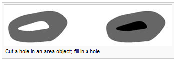
- a: Cut a hole in an area object, b: Fill in a hole
 Cut a Hole

![]() Cut Area:
Cut Area:
- This function is enabled when an area object is selected.
- Choose this function to split an area into two objects.
- Split an area object
- You can use the Curve, Straight line, Rectangular line or Freehand mode to split an area object into two objects.
- Select the area object to cut.
- Select a drawing mode (Curve, Straight line, Rectangular or Freehand).
- Click the
 Cut Area button.
 - Draw the cut line. It must start at the border of the area, go across the area and end at the border of the area.
- The area is now split into two objects. Note that the cut line should not cross a hole. Otherwise the hole may not be treated correctly for the 2 resulting objects.
- After cutting the area object always the smaller of the two new area objects is selected.
- Change drawing mode with the Tab key before starting to cut.
![]() Cut Line:
Cut Line:
- This function is enabled when a line or an area object with border line is selected.
- Choose this button to divide a line into 2 objects or to cut a Virtual gap into a line object (introduced in OCAD 10), i.e. the line object is not divided, the gap concerns only graphic representation of the object.
- Split a line object
- Click on the desired position anywhere on the line. The line is then split into 2 objects. One of them is selected.
- You can use this function to influence the dashes of a dashed line.
- Split a line object with cut-out
- Instead of just splitting you can create a cut-out (a gap) in the line.
- Click on the
 Cut button.
 - Place the mouse pointer at the start point of the cut.
- Press and hold down the left mouse button.
- Move the mouse pointer to the end of the cut.
- Release the mouse button. The object is now divided into two and the cut-out portion is deleted.
- -If you press the Ctrl key when cutting a line, the line is not divided into 2 objects. A Virtual gap concerning only the graphic representation of the object is inserted.
- -If you press the Shift key when cutting a dashed line, you insert a gap with the same length, as the other gaps in the dashed line.
- -It is possible to cut a part of the individual sidelines of double line symbols (like major roads), without having to cut the entire line itself.
Crop Objects
Visit the Crop Objects page to find some information about the Crop Objects button.
Move Parallel
Visit the Move Parallel page to find some information about the ![]() Move Parallel and the Move Parallel with Distance function.
Move Parallel and the Move Parallel with Distance function.
Reshape
Visit the Reshape page to find some information about the ![]() Reshape function.
Reshape function.
Interpolate Objects
Visit the Interpolate Objects page to find some information about the ![]() Interpolate Objects function.
Interpolate Objects function.
Duplicate
A description of the ![]() Duplicate function can be found on the Duplicate page.
Duplicate function can be found on the Duplicate page.
Move and Duplicate
Visit the Move and Duplicate page to get some information about this function.
Mirror and Duplicate
Visit the Mirror and Duplicate page to get some information about this function.
Fill or Make Border or Duplicate Identically
You can find this functions either in the Object menu or you can click the corresponding button ![]() in the Edit Functions Toolbar.
in the Edit Functions Toolbar.
This function is enabled when an object is selected on the map and a symbol is selected in the symbol box which is compatible with the selected object. For example, areas can be filled with other areas, or surrounded with line objects but you cannot fill them with point objects. With this function it is possible to do several things:
- If you use this function when you have selected an object with the same symbol as selected in the symbol box, an identical copy of the object at the same position is made.
- If you use this function when you have selected an object with the same symbol type as the symbol selected in the symbol box (e.g both are area, line, text or point symbols), a copy of the object is made at the same position and the selected symbol in the symbol box is assigned to this new object.
- If you use this function when you have selected an area object in the drawing area and a line symbol in the symbol box, a border line around the area object is created.
- The other way round, if you use this function when you have selected a line object in the drawing area and an area symbol in the symbol box, the line object is filled with the area symbol.
- If you use this function when you have selected a hole, the hole is filled if you have selected an area in the symbol box or a border line is created if you have selected a line in the symbol box. Read more about holes here.
Merge
You can find this function in the Object menu or by clicking the ![]() Merge button in the Edit Functions Toolbar.
Merge button in the Edit Functions Toolbar.
With this function you can merge the selected objects. It is enabled if two or more line, area or text objects with the same symbol are selected.
Merge Line Objects
To merge line objects, the start respectively the end points of the selected lines must be close together (at most 0.25 mm). The resulting objects may have up to 4'000'000 vertices.
Merge Area Objects
To merge area objects, the selected area objects have to overlap.
Merge Text Objects
If you merge text objects, the text parts are positioned with a line break under the first text.
- When drawing line or area objects, you can continue existing line or area objects, instead of merging them afterwards. To do this, keep the Shift key pressed and start drawing at the first or last vertex of the existing object.
Reverse Object Direction
You can find this function in the Object menu or by clicking the ![]() Reverse Object button in the Edit Functions Toolbar.
Reverse Object button in the Edit Functions Toolbar.
This function is enabled when a line, line text or area object is selected. It will reverse the direction of the object, the first vertex becomes the last one and vice versa.
Reverse object direction function is useful for objects with asymmetrical line symbols. If a line or borderline has tags to the right side, the tags will point to the left side after reversing. Line text appears on the other side of the line.

Add Vertices
Select Add Vertex in Object Menu
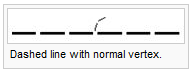
Normal Vertex:
- This button is enabled when a line or area object is selected. When you click on this button, the button remains pressed and the mouse pointer shows the same symbol when it is moved to the drawing window.
- When this mode is selected, you can insert additional normal vertices or change existing vertices to normal vertices.
- Inserting normal vertices
- Move the mouse pointer to the desired position on a line object or on the border of an area object and click the left mouse button. A new normal vertex is inserted. However, if there is already a vertex in this position, the existing vertex is converted to a normal vertex and no additional vertex is inserted.
- You can also insert normal vertices in Select and Edit object or Select Object and Edit Vertex mode when holding down both the
 and the Ctrl key.
- Change a vertex to a normal vertex
- Move the mouse pointer to the vertex to be converted and click the left mouse button. The vertex is changed to a normal vertex.
Corner Vertex:
- A corner vertex is a special vertex of line and area objects. Corner vertices have 3 effects:
- they influence how line objects are drawn
- they influence the editing of Bézier curves
- when smoothing (automatically or manually) they remain in the same position
- When an object is selected, corner vertices are marked with an empty rectangle (
 ).
).
- Corner vertex are automatically created when drawing in the straight line mode (when the Straight line button is pressed).
- When the Corner vertex button is pressed, corner vertex can be inserted or normal vertices can be changed to corner vertices.
- When the Normal vertex button is pressed, corner vertex can be converted to normal vertices.
- Influence on line objects
Corner vertex influence structured line objects such as dashed lines. When OCAD renders a dashed line it distributes dashes of equal length on that line. Corner vertex divide a line into several line sections. OCAD distributes the dashes on each section as if it were an individual object.


- Influence on Bézier curves
- Corner vertex allow you to create corners in Bézier curves. The Curve vertex before and after a corner vertex can be moved individually without influencing each other. This allows you to create sharp corners.
- This button is enabled when a line or area object is selected. When clicking on this button the button remains pressed and the mouse pointer shows the same symbol when it is moved to the drawing window.
- When this mode is selected you can insert additional corner vertices or change existing vertices to corner vertices.
- Inserting corner vertex
- Move the mouse pointer to the desired position on a line object or on the border of an area object and click the left mouse button. A new corner vertex is inserted. However, if there is already a vertex in this position the existing vertex is converted to a corner vertex and no additional vertex is inserted.
- Change a vertex to a corner vertex
- Move the mouse pointer to the vertex to be converted and click the left mouse button. The vertex is changed to a corner vertex.
- Dash vertex:
- A dash vertex is a special vertex of line or area objects. Dash vertices influence how line objects are rendered. When an object is selected, dash vertices are marked with a diamond (
 ).
). - When the Dash vertex button is pressed, dash vertices can be inserted or normal vertices can be converted to dash vertices.
- When the Normal vertex button is pressed, dash vertices can be converted to normal vertex.
- Influence on line objects
- Dash vertexes influence structured line objects such as dashed lines. When OCAD renders a dashed line it distributes dashes of equal length on that line. Insert a dash vertex to force a dash to a certain position.


- This button is enabled when a line or area object is selected. When you click on this button the button remains pressed and the mouse pointer shows the same symbol when it is moved to the drawing window.
- When this mode is selected you can insert additional dash vertices or change existing vertices to dash vertices.
- Inserting dash vertices
- Click on the Dash vertex button, and then move the mouse pointer to the desired position on a line object or on the border of an area object and click the left mouse button. A new dash vertex is inserted. However, if there is already a vertex in this position the existing vertex is converted to a dash vertex and no additional vertex is inserted.
- Change a vertex to a dash vertex
- Click on the Dash vertex button, and then move the mouse pointer to the vertex to be converted and click the left mouse button. The vertex is changed to a dash vertex.
Remove Vertex
![]() Remove Vertex button
Remove Vertex button
This button is enabled when a line or area object is selected. When you click on this button, the button remains pressed and the mouse pointer shows the same symbol when it is moved to the drawing window.
When this mode is selected, you can remove a vertex from a line or area object. Move the mouse pointer on the desired vertex and click the left mouse button.
You can also remove vertices in Select and Edit object or Select Object and Edit Vertex mode when holding down the Ctrl key.
Change Vertex Types to
Select Change Vertex Types to in Object Menu
Choose this command to change the symbol of all objects with a symbol A to symbol B. The Change Symbol of Objects dialog box is displayed.
This command is especially useful to translate the layers of an imported file to OCAD symbols.
- Change all objects with: Enter here the symbol number or the name of the layer of the objects to be changed. If an object is selected this edit box initially contains the symbol number or the layer name of the selected object.
- To symbol no.: Enter here the new symbol number to be given to the objects. Initially this edit box contains the number of the currently selected symbol This command is enabled when 1 or more objects are selected. This command will change the specified vertex types of all the selected objects in one step.
- Normal vertex: The Change Vertex Types dialog box is opened. Check the vertex types (normal, corner, dash, virtual gap) that should be changed to normal vertex. Click OK button to execute this command.
- Corner vertex: The Change Vertex Types dialog box is opened. Check the vertex types (normal, corner, dash, virtual gap) that should be changed to corner vertex. Click OK button to execute this command.
- Dash vertex: The Change Vertex Types dialog box is opened. Check the vertex types (normal, corner, dash, virtual gap) that should be changed to dash vertex. Click OK button to execute this command.
Find and Replace Text
Choose this command to find and replace text of objects. The Find and Replace Text dialog box is displayed.
Find text
- Enter a text you want to find.
- Choose Case sensitive option if find function should consider case sensitivity.
- Choose Whole words only option if find function should only succeed if find text is equal to a whole word.
- Click Find button to start find function.
Replace with
- Enter a text that should replace find text.
- Click Replace button to replace text in last found object. Click Replace all button to replace text in all objects where find function matches.
Measure
![]() This command is enabled when line or area objects or 2 point objects are selected.
This command is enabled when line or area objects or 2 point objects are selected.
Choose this command to measure the length of the selected line object(s), the area of the selected area object(s) or the distance between 2 point objects. The result is displayed in the Measure Result dialog box. The displayed length or area is the sum of the selected objects line length or area.
The map scale is used for the calculation.
Object Information
This command is enabled if at least 1 object is selected.
Choose this command to get more information about the selected object(s). The following information is shown in the Object Information dialog:
- Object index
- Server object index
- Object type
- Symbol
- Color
- Number of vertices
- Elevation [m]
- Length [m]
- Area [m2]
- Coordinates [mm] or [m] (only if 1 object is selected)
Previous Chapter: Select
Next Chapter: Layout
Back to Main Page